bnp-b2365(eng)b.pdf - 第281页
5. Spindle Adjustment 5 - 36 5-3-3 Adjusting the orientation control (1) Confirming the default parameters Set the default parameters for each det ector u sed in o rientation con trol. (a) Motor PLG Motor PLG orientation…
5. Spindle Adjustment
5 - 35
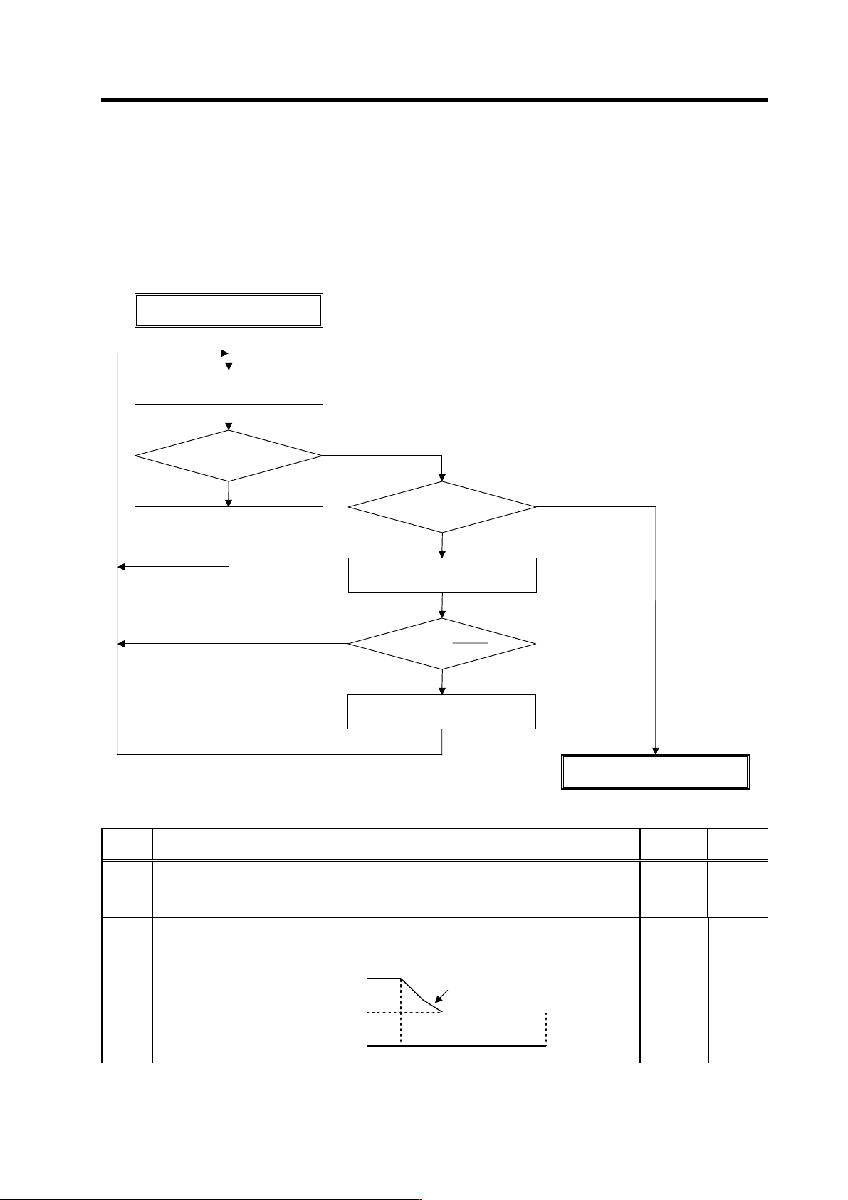
(9) Adjusting deceleration time
When the deceleration time "td" is significantly different from the acceleration time "ta" (td < 0.95 × ta,
1.1 × 1a < td) and no problem with the acceleration time, adjust the deceleration time by changing
the target value of variable torque limit magnification at deceleration (SP087) setting. In cases,
however, where the variable torque characteristic cannot be lowered to the SP087 level, adjust by
changing the speed for starting change of variable torque limit magnification at deceleration (SP088)
setting.
No. Abbr. Parameter name
Details
Setting
range
Standard
SP087 DIQM* Target value of
variable torque limit
magnification at
deceleration
Set the minimum value of variable torque limit at deceleration. 0 to 150
(%)
75
Set the speed where the torque limit value at deceleration
starts to change.
Torque limit
Inversely proportional to
speed
SP088 DIQN*
Speed for starting
change of variable
torque limit
magnification at
deceleration
100%
SP087
SP088 SP017 Speed
0 to 32767
(r/min)
3000
Adjusting SP087, SP088
td > 1.1 × ta?
SP087, SP088 adjustment completed
Increase SP087 by +5.
YES
NO
Measure acceleration/deceleration
waveform at high speed
td < 0.95 × ta?
Increase SP087 by –5.
YES
NO
SP087<100 × – ?
SP088
SP017
Increase SP088 by –500.
YES
NO
5. Spindle Adjustment
5 - 36
5-3-3 Adjusting the orientation control
(1) Confirming the default parameters
Set the default parameters for each detector u sed in o rientation control.
(a) Motor PLG
Motor PLG orientation is possible only when the spindle and motor are coupled, or when they
are coupled 1:1 with gears (timing belt). The SP025 (GRA1) to SP032 (GRB4) parameters can
be set only to 1. The PLG with Z-phase must be mounted on the motor to be used.
(b) Spindle end detector
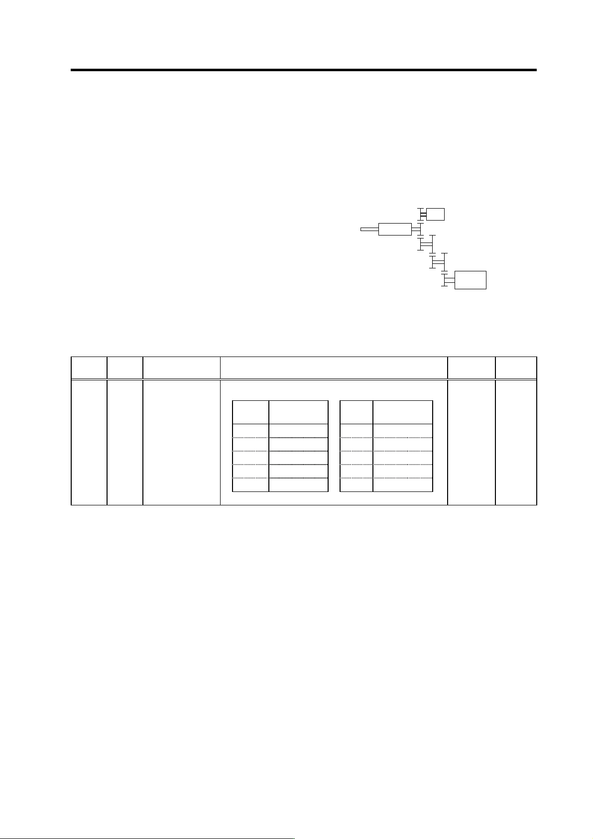
An accurate gear ratio (pulley ratio) is required from
the motor shaft to the spindle end detector rotary
axis.
Make sure that the correct number of gear teeth is
set in SP025 (GRA1) to SP032 (GRB4).
SP025 to SP028=A × C × E
SP029 to SP032=B × D × F
Set the gear ratio (A:X) between the spindle and
spindle end detector in SP 096 (EGAR).
No. Abbr. Parameter name Details
Setting
range
Standard
Set the gear ratio between the spindle end and the detector end
(except for the motor PLG) as indicated below.
Setting
value
Gear ratio
(deceleration)
Setting
value
Gear ratio
(acceleration)
0 1 : 1 -1 1 : 2
1 1 : 1/2 -2 1 : 4
2 1 : 1/4 -3 1 : 3
3 1 : 1/8
4 1 : 1/16
SP096 EGAR* Encoder gear ratio -3 to 4 0
S
p
indle end detecto
r
XS
p
indle
Spindle
moto
r
A
BC
D E
F
Spindle configuration when using
spindle end detecto r
5. Spindle Adjustment
5 - 37
(c) Magnetic sensor
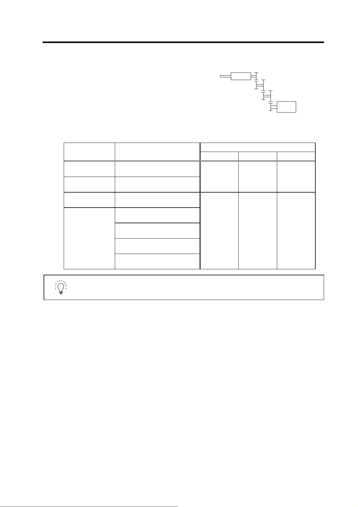
An accurate gear ratio (pulley ratio) is required from
the motor shaft to the detector rotary axis. Make sure
that the correct number of gear teeth is set in SP025
(GRA1) to SP032 (GRB1).
SP025 to SP028=A × C × E
SP029 to SP032=B × D × F
The SP123 (MGD0) to SP125 (MGD2) parameters
are set as shown below according to the magnetic
sensor type.
Parameter setting
Type Magnetic sensor type
SP123 (MGD0) SP124 (M GD1) SP125 (MGD2)
Standard
MAGNETIC SENSOR
BKO-C1810H01-3
High-speed standard
MAGNETIC SENSOR
BKO-C1730H01.2.6
542 768 384
High-speed compact
MAGNETIC SENSOR
BKO-C1730H01.2.9
MAGNETIC SENSOR
BKO-C1730H01.2.41
MAGNETIC SENSOR
BKO-C1730H01.2.42
MAGNETIC SENSOR
BKO-C1730H01.2.43
High-speed ring type
MAGNETIC SENSOR
BKO-C1730H01.2.44
500 440 220
POINT
When using the magnetic sensor, orientation control cannot be carried out with
a machine having a gear ratio between the spindle motor and spi ndle exceeding
1:31.
S
p
indle
Spindle
moto
r
A
B C
D E
F
Spindle configuration when using
magnetic sensor