bnp-b2365(eng)b.pdf - 第294页
5. Spindle Adjustment 5 - 49 [4] The stopping position does not change even when the position shift parameter is change d. Cause Investigati on item Remedy Remarks 1 Parameter settin g values are incorrect The position s…

5. Spindle Adjustment
5 - 48
(5) Troubleshooting
[1] Orientation does not take place (motor keeps rotating)
Cause Investigation item Remedy Remarks
1 Parameter setting
values are incorrect
The orientation detector and
parameter do not match.
SP037 (SFNC5)
Motor PLG.............................. 4
Spindle end detector .............. 1
Magnetic sensor..................... 2
Correctly set SP037 (SFNC5).
2 The specification are
not correct
Motor PLG orientation is attempted
with standard motor instead of motor
with Z phase.
Change to a motor having a
PLG-built-in motor with Z phase.
For motor PLG
orientation
3 Incorrect wiring The connector pin numbers are
incorrect,
The inserted connector number is
incorrect.
The cable is disconnected.
Correct the wiring.
Replace the cable.
[2] The motor overtravels and stops. (The motor sways when stopping.)
Cause Investigation item Remedy Remarks
1 Parameter setting
values are incorrect
The gear ratio parameters:
SP025 (GRA1) to SP032 (GRB4) are
incorrect.
Correctly set SP025 (GRA1) to
SP032 (GRB4).
The phenomenon is improved when
the deceleration rate for orientation
parameter SP006 (CSP) is halved.
Readjust SP006 (CSP) This also applies to:
SP107 (CSP2)
SP108 (CSP3)
SP109 (CSP4)
SP121 (MPCSH)
SP122 (MPCSL)
The phenomenon is improved when
the position loop gain parameters
SP001 (PGM) and SP002 (PGE) are
halved.
Readjust SP001 (PGM), SP002
(PGE).
This also applies to:
SP119 (MPGH)
SP120 (MPGL)
The orientation stop direction is set to
one direction (CCW or CW).
Set the SP097 (SPECO) /bit 0, 1
to "0".
[3] The stopping position deviates.
Cause Investigation item Remedy Remarks
1 Mechanical cause The stopping position is not deviated
with the encoder axis.
There is backlash or slipping, etc.,
between the spindle and encoder.
The gear ratio between the
spindle and encoder is not 1:1 or
1:2.
For spindle end
detector orientation
There is backlash or slipping
between the spindle and motor.
The gear ratio between the
spindle and motor is not 1:1.
For motor PLG
orientation
2 Noise The position detector's cable is
relayed with a terminal block
(connector), etc.
Do not relay the cable.
The position detector cable's shield is
not treated properly.
Properly treat the shield.
The peeled section of signal wire at
the position detector cable's connector
section is large. (A large section is not
covered by the shield.)
Keep the peeled section to 3cm or
less when possible. Keep the
peeled section as far away from
the power cable as possible.
3 The magnetic sensor
installation direction is
incorrect
Check the relation of the magnet and
sensor installation.
Correct the relation of the magnet
and sensor installation.
For magnetic sensor
orientation.

5. Spindle Adjustment
5 - 49
[4] The stopping position does not change even when the position shift parameter is change d.
Cause Investigation item Remedy Remarks
1 Parameter setting
values are incorrect
The position shift was changed to
2048 when the gear ratio between the
spindle and encoder was 1:2 (one
encoder rotation at two spindle
rotations).
If the gear ratio on the left is
established between the spindle
and encoder, the position shift
amount for one spindle rotation is
2048 instead of 4096.
[5] The machine vibrates when stopping.
Cause Investigation item Remedy Remarks
1 Parameter setting
values are incorrect
The gear ratio parameters SP025
(GRA1) to SP032 (GRB4) are
incorrect.
Correctly set SP025 (GRA1) to
SP032 (GRB4).
2 The orientation
adjustment is faulty
The vibration frequency is several Hz. Decrease the position loop gain
parameters SP001 (PGM) and
SP002 (PGE).
Increase the current loop gain for
orientation parameters SP105
(IQGO) and SP106 (IDGO).
The vibration frequency is 10Hz or
more.
Decrease the speed loop gain for
orientation parameters SP098
(VGOP) and SP099 (VGOI).
Decrease the current loop gain for
orientation parameters SP105
(IQGO) and SP106 (IDGO).
[6] The orientation complete signal is not output
Cause Investigation item Remedy Remarks
1 The machine's load is
heavy
The in-position parameter SP004
(OINP) is too small.
Review the in-position range, and
increase SP004 (OINP).
State is improved if delay
compensation control is stopped
during orientation stopping.
(State is improved when changed to
PI control).
Review the values set for the
speed loop gain for orientation
parameters SP098 (VGOP),
SP099 (VGOI) and SP100
(VGOD).
2 Carry out the items for [1] Orientation does not take place (motor keeps rotating).
5. Spindle Adjustment
5 - 50
5-3-4 Adjusting the synchronous tap control
(1) Confirming the default parameters
Confirm that the parameters are correctly set according to the machine specifications. Pay special
attention to the following points.
(a) Position loop gain
The position loop gain must be the same as the servo axis used for interpolation control during
synchronous tap control.
Position loop gain for synchronou s tap control SP009 = SV049
Position loop gain 2 for synchronous t ap control SP221 = SV050
Position loop gain 3 for synchronous t ap control SP222 = SV058
(b) High-gain servo synchronous compensation
The synchronous tap control specifications SP193/bit8 must be set according to the
specification of the servo drive unit used for interpolation control during synchronous tap
control.
Synchronous compensation valid = High-gain servo :
MDS-C1-V1/V2 (for high-gain setting), MDS-B-V14/V24
Synchronous compensatio n invalid = Standard servo :
MDS-C1-V1/V2 (for standard setting), MDS-B-V 1/V2, MDS-B-SVJ2
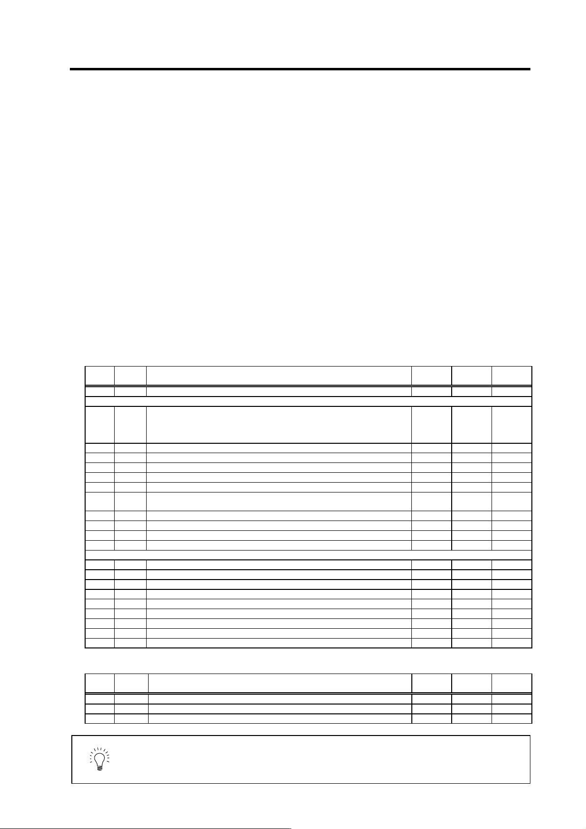
<Spindle parameters>
No. Abbrev. Parameter name Unit
Setting
range
Standard
value
SP009 PGT Synchronized tapping Position loop gain rad/s 1 to 100 15
SP193 SPECT*
Synchronized tapping specifications
(The standard value is set according to the servo drive for interpolation
control.)
HEX
0000 to
FFFF
Standard:
0000
High-gain:
0100
SP194 VGTP* Synchronized tapping speed loop gain proportional term 0 to 1000 63
SP195 VGTI* S ynchronized tapping speed loop gain integral term 0 to 1000 60
SP196 VGTD* Synchronized tapping speed loop gain delay advance term 0 to 1000 15
SP197 Fixed control constant 0 0
SP198 VCGT* Synchronized tapping target value of variable speed loop proportional gain % 0 to 100 100
SP199 VCST*
Synchronized tapping change starting speed of variable speed loop
proportional gain
r/min 0 to 32767 0
SP200 FFC1* Synchronized tapping acceleration feed forward gain (gear 1) % 0 to 1000 0
SP201 FFC2* Synchronized tapping acceleration feed forward gain (gear 2) % 0 to 1000 0
SP202 FFC3* Synchronized tapping acceleration feed forward gain (gear 3) % 0 to 1000 0
SP203 FFC4* Synchronized tapping acceleration feed forward gain (gear 4) % 0 to 1000 0
SP214 TZRN Synchronized tapping zero point return speed r/min 0 to 500 50
SP215 TPDT Synchronized tapping zero point return deceleration rate pulse 0 to 10000 1
SP216 TPST Synchronized tapping zero point return shift amount 0 to 4095 0
SP217 TINP Synchronized tapping in-position width 1/16 deg 1 to 2880 16
SP218 TODR* Synchronized tapping excessive error width (1pulse=0.088deg) pulse 0 to 32767 32767
SP219 IQGT* Synchronized tapping current loop gain magnification 1 % 0 to 1000 100
SP220 IDGT* Synchronized tapping current loop gain magnification 2 % 0 to 1000 100
SP221 PG2T Synchronized tapping position loop gain 2 rad/s 0 to 999 0
SP222 PG3T Synchronized tapping position loop gain 3 rad/s 0 to 999 0
<Servo parameters>
No. Abbrev. Parameter name Unit
Setting
range
Standard
value
SV049 PGN1sp Position loop gain 1 in spindle synchronous control rad/s 1 to 200 15
SV050 PGN2sp Position loop gain 2 in spindle synchronous control rad/s 0 to 999 0
SV058 SHGCsp SHG control gain in spindle synchronous control rad/s 0 to 1200 0
POINT
Always adjust the synchron ous tap control after adjusting the ope ration and
acceleration/deceleration time with the speed command, and adjusting the
servo axis controlled in synchronizatio n with the spindle du ring synchron ous tap
control.