bnp-b2365(eng)b.pdf - 第302页
5. Spindle Adjustment 5 - 57 5-3-6 Adjusting the spindle synchronous control (1) Confirming the default parameters Confirm that the parameters are correctly set accordin g to the machine specifications. The parameters ar…
5. Spindle Adjustment
5 - 56
(3) Disturbance observer
The disturbance observer estimates the disturbance torque and compensate s accordi ngly, thereby
minimizing cutting time disturbance, frictional resi stan ce, and torsion vibration. It is also effective in
suppressing vibration that is caused by spe ed advance compensation control.
The disturbance observer function is enabled in all control modes (not just the C-axis control)
during a spindle control input 4/bitF=1 (increased spindle hold force). The position loop gain and
speed loop gain settings a re set separately during disturbance observer operation.
<Setting method>
[1] Calculate the inertia for all axes including the spindle motor, then set the motor inertia rate as
the disturbance observer load inertia rate (SP233) value.
[2] Set the disturbance observer low path filter frequency (SP234) to the observer filter band
(observer pole) value to suppress the estimated high-frequency disturbance and vibration. The
standard setting is "100".
[3] Set the disturbance observer gain (SP235) to the observer gain value. This activates the
disturbance observer function. Begin with a setting of "100", then, if no vibration occurs,
increase the setting value in increments of "50" to increase the com pensation efficacy.
[4] If the disturbance observer setting facilitates vibration, decrease the speed loop gain
proportional item for increased spindle holding force (SP168) and the speed loop gain integral
item for increased spindle holdin g force (SP169) values by 10 to 20% at the same rate.
[5] Although the position loop gain can be set individually by the position loop gain for increased
spindle holding force (SP167) setting during disturbance observer operation, it should be set to
the same value as the other settings if the interpolati on servo axis is performing SHG control.
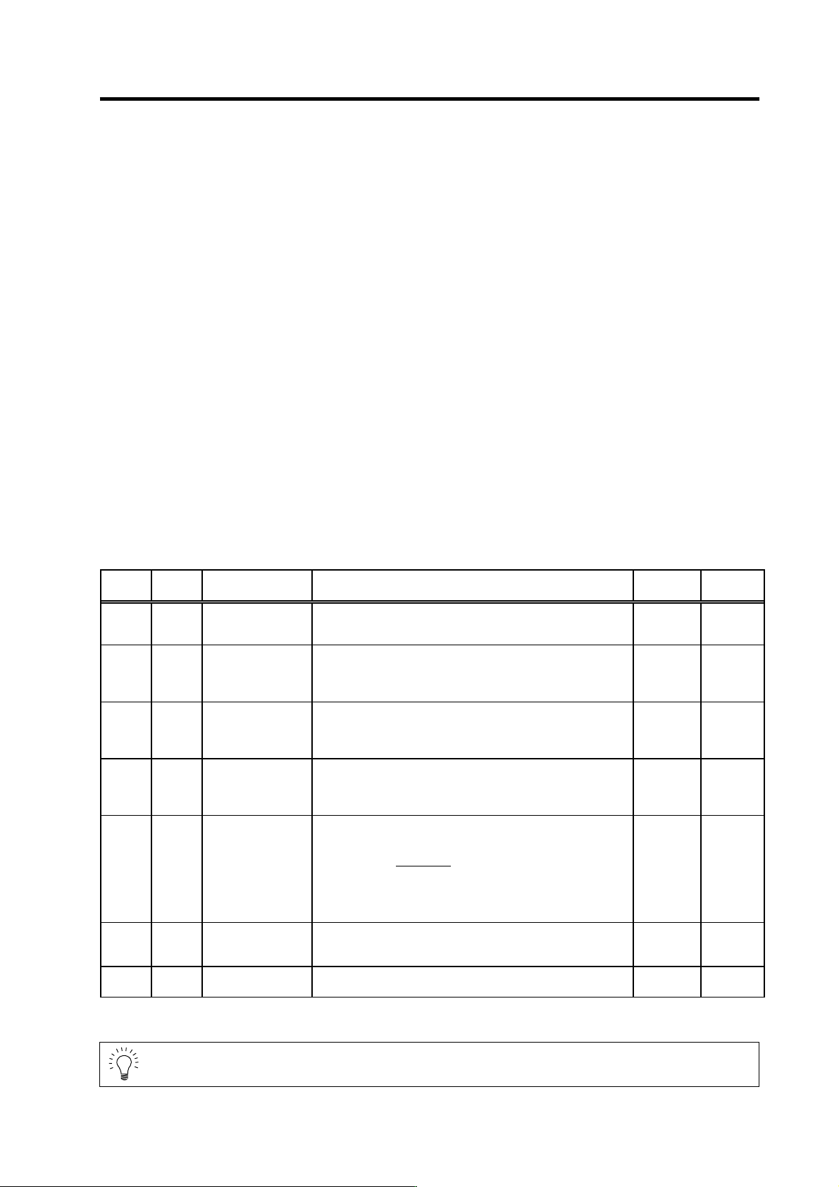
No. Abbr. Parameter name Details
Setting
range
Standard
SP167 PGU* Position loop gain for
increased spindle
holding force
Set the position loop gain for when the disturbance observer is
valid.
0 to 100
(rad/s)
15
SP168 VGUP* Speed loop gain
proportional item for
increased spindle
holding force
Set the speed loop gain proportional item for when the
disturbance observer is valid.
0 to 5000 63
SP169 VGUI* Speed loop gain
integral item for
increased spindle
holding force
Set the speed loop gain integral item for when the disturbance
observer is valid.
0 to 5000 60
SP170 VGUD* Speed loop gain
delay advance item
for increased spindle
holding force
Set the speed loop gain delay advance item for when the
disturbance observer is valid.
0 to 5000 15
Set "the motor inertia + motor axis conversion load inertia" in
respect to the motor inertia.
Jl+Jm
SP233 (JL)=
Jm
×100
SP233 JL* Disturbance
observer Load inertia
rate
Jm
Jl
: Motor inertia
: Motor axis conversion load inertia
0 to 5000
(%)
0
SP234 OBS1* Disturbance
observer low path
filter frequency
Set the frequency of the low path filter for when the disturbance
observer is valid.
0 to 1000
(rad/s)
0
SP235 OBS2* Disturbance
observer gain
Set the gain for the disturbance observer. 0 to 500
(%)
0
POINT
Disturbance observer control is valid in all control modes d uring a spindle control
input 4/bitF.
5. Spindle Adjustment
5 - 57
5-3-6 Adjusting the spindle synchronous control
(1) Confirming the default parameters
Confirm that the parameters are correctly set according to the machine specifications. The
parameters are set with the following co nditions for spindles used for synchronous control.
(a) Position loop gain
The same value must be set for the spindle drive units used for synchronous co ntrol.
Spindle synchronous position loop gain : SP010
Spindle synchronous position loop gain 2 : SP189
Spindle synchronous position loop gain 3 : SP190
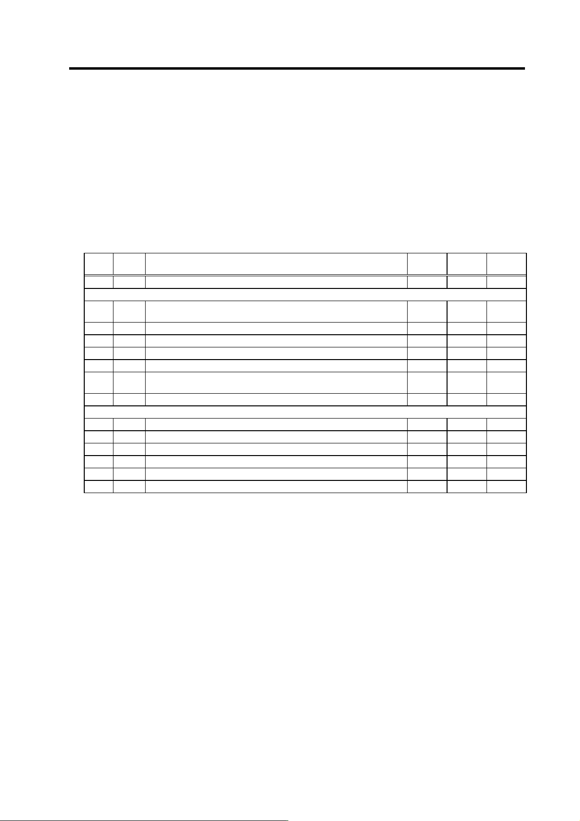
<Spindle parameters>
No. Abbr. Parameter name Unit
Setting
range
Standard
value
SP010 PGS Spindle synchronization position loop gain rad/s 1 to 100 15
SP177 SPECS* Spindle synchronous specifications HEX
0000 to
FFFF
0000
SP178 VGSP* Spindle synchronous speed loop gain proportional term 0 to 1000 63
SP179 VGSI* Spindle synchronous speed loop gain integral term 0 to 1000 60
SP180 VGSD* Spindle synchronous speed loop gain delay advance term 0 to 1000 15
SP181 VCGS* S pindle synchronous Targ e t va l u e of va r i a b le sp e e d lo o p pr o p or t i o na l g a i n % 0 to 100 100
SP182 VCSS*
Spindle synchronous Change starting speed of variable speed loop
proportional gain
r/min 0 to 32767 0
SP183 SYNV Spindle synchronous Sync matching speed r/min 0 to 1000 20
SP185 SINP Spindle synchronous In-position width 1/16 deg 1 to 2880 16
SP186 SODR* Spindle synchronous Excessive error width (1pulse=0.088deg) pulse 0 to 32767 32767
SP187 IQGS* Spindle synchronous Current loop gain magnification 1 % 0 to 1000 100
SP188 IDGS* Spindle synchronous Current loop gain magnification 2 % 0 to 1000 100
SP189 PG2S Spindle synchronous Position loop gain 2 rad/s 0 to 999 0
SP190 PG3S Spindle synchronous Position loop gain 3 rad/s 0 to 999 0
5. Spindle Adjustment
5 - 58
(2) Setting the multi-step acceleration/deceler ation time constant
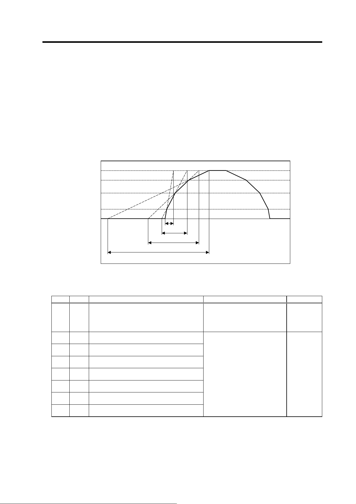
For acceleration/deceleration control during spindle synchronous control, the acceleration/
deceleration time constant can be set up to eight steps according to the spindle rotation speed.
The acceleration/deceleration time constant (acceleration time from 0 to limit rotation speed slimit)
for each step is set as shown below based on the time constant set for the first step.
1st stage a cceleratio n/deceleration time constant : TC1 = spt
2nd stage a c celeration/deceleration time con stant : TC2 = spt × spdiv1
3rd stage acceleratio n/de celeration time const ant : TC3 = spt × spdiv2
4th stage acceleratio n/deceleration time constant : TC4 = spt × spdiv3
5th stage acceleratio n/deceleration time constant : TC5 = spt × spdiv4
6th stage acceleratio n/deceleration time constant : TC6 = spt × spdiv5
7th stage acceleratio n/deceleration time constant : TC7 = spt × spdiv6
8th stage acceleratio n/deceleration time constant : TC8 = spt × spdiv7
Multi-step acceleration/decelera tion control for spindle synchronous control (for 4-step setting)
<Spindle specification parameters>
No. Abbr. Parameter name Details Setting range
3049 spt Spindle synchronization acceleration/deceleration
time constant
Set the acceleration/deceleration time
constant for when the spindle
synchronization command's rotation
speed changes during spindle
synchronous control.
0 to 9999
(ms)
3054 sptc1 Spindle synchronization multi-step
acceleration/deceleration changeover speed 1
3055 sptc2 Spindle synchronization multi-step
acceleration/deceleration changeover speed 2
3056 sptc3 Spindle synchronization multi-step
acceleration/deceleration changeover speed 3
3057 sptc4 Spindle synchronization multi-step
acceleration/deceleration changeover speed 4
3058 sptc5 Spindle synchronization multi-step
acceleration/deceleration changeover speed 5
3059 sptc6 Spindle synchronization multi-step
acceleration/deceleration changeover speed 6
3060 sptc7 Spindle synchronization multi-step
acceleration/deceleration changeover speed 7
Set the spindle speed for changing the
Nth step's acceleration/deceleration
time constant.
0 to 99999
(r/min)
TC2
0
TC1=s
p
t
Time
s
p
tc3
Slimit = s
p
tc4
s
p
tc1
s
p
tc2
TC3
TC4
Spindle speed