bnp-b2365(eng)b.pdf - 第305页
5. Spindle Adjustment 5 - 60 (3) Adjusting the multi-step acceleration/deceler ation time constants [1] Measure the acceleration/deceleration wavefo rm to the spindle's m aximum rotation speed using S command operat…

5. Spindle Adjustment
5 - 59
No. Abbr. Parameter name Details Setting range
3061 spdiv1 Magnification for time constant changeover speed 1
3062 spdiv2 Magnification for time constant changeover speed 2
3063 spdiv3 Magnification for time constant changeover speed 3
3064 spdiv4 Magnification for time constant changeover speed 4
3065 spdiv5 Magnification for time constant changeover speed 5
3066 spdiv6 Magnification for time constant changeover speed 6
3067 spdiv7 Magnification for time constant changeover speed 7
Set the acceleration/deceleration time
constant in the spindle synchronization
multi-step acceleration/deceleration
changeover speed sptc (N) to sptc
(N+1) range.
Set the time that the spindle speed
accelerates from 0 to slmit as a
magnification in respect to the spindle
synchronization
acceleration/deceleration time
constant (spt).
When spdiv7 is set, the range is sptc7
to slimit.
0 to 127
5. Spindle Adjustment
5 - 60
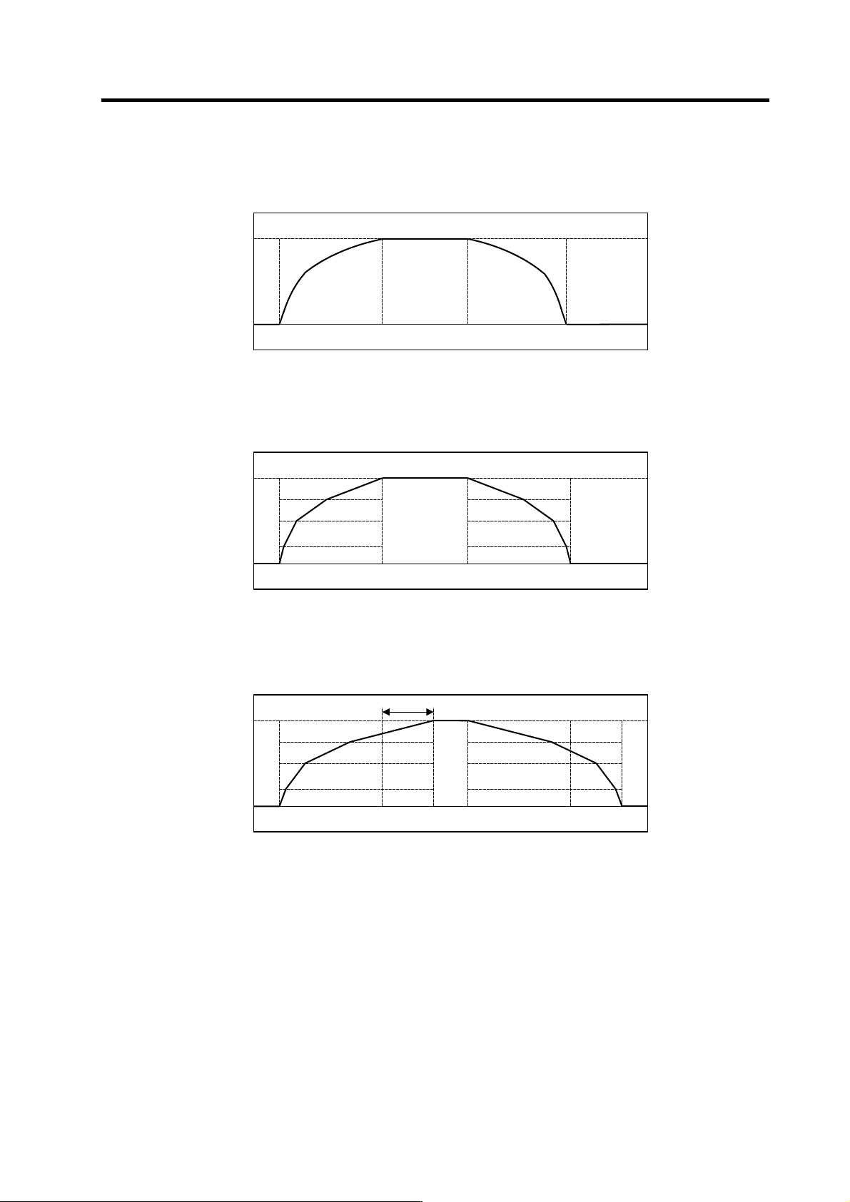
(3) Adjusting the multi-step acceleration/deceleration time constants
[1] Measure the acceleration/deceleration waveform to the spindle's maximum rotation speed
using S command operation. (No. 1 spindle, No. 2 spindle)
Example of spindle acceleration/deceleration wa veform
[2] Calculate the multi-step acceleration/deceleration pattern based on the acceleration/
deceleration waveform for the spindle with a long acceleration/deceleration time.
Calculation of multi-step acceleration/deceleration
[3] Set the actual acceleration/deceleration time constant in the parameters while maintaining a
50% margin from each time constant calculated in step [2].
Setting the multi-step acceleration/deceleration parameters
[4] Try spindle synchronous acceleration/deceleration operation with the actual machine, and
confirm that the speed is accelerated or decelerated at 50% or less of the load meter value. If
the load meter value exceeds 50%, adjust the time constant again.
0
Time
10000
Speed FB
(r/min)
0
Time
10000
Speed FB
(r/min)
1-step
2-step
3-step
4-step
0
Time
10000
Maintaining a 50% margin
Speed FB
(r/min)

6. Troubleshooting
6 - 1
6-1 Points of caution and confirmation ................................................................................................... 6-2
6-1-1 LED display when alarm or warning occurs .............................................................................. 6-3
6-2 Protective functions list of units ........................................................................................................ 6-4
6-2-1 List of alarms.............................................................................................................................. 6-4
6-2-2 List of warnings .......................................................................................................................... 6-9
6-3 Troubleshooting .............................................................................................................................. 6-10
6-3-1 Troubleshooting at power ON.................................................................................................. 6-10
6-3-2 Troubleshooting for each alarm No. ...................................................................................... .. 6-11
6-3-3 Troubleshooting for each warning No......................................................................................6-40
6-3-4 Parameter numbers during initial parameter error................................................................... 6-44
6-3-5 Troubleshooting the spindl e system when there is no alarm or warning................................. 6-45