bnp-b2365(eng)b.pdf - 第310页
6. Troubleshooting 6 - 5 Drive unit alarm No. Alar m n ame SV SP Alarm det ails Reset 20 Motor side detect or , No signal 1 { A PLG Z-phase n o signal was detected. PR 21 Machine side detector, No signal 2 § { The pulse-…
6. Troubleshooting
6 - 4
6-2 Protective functions list of units
6-2-1 List of alarms
When an alarm occurs, the servo drive unit will make the motor stop by the deceleration control or
dynamic brake. The spindle drive unit will coast to a stop or will decelerate to a stop. At the same time,
the alarm No. will appear on the NC monitor screen and with the LEDs on the front of the drive unit.
Check the alarm No., and remove the cause of the ala rm by followin g this list.
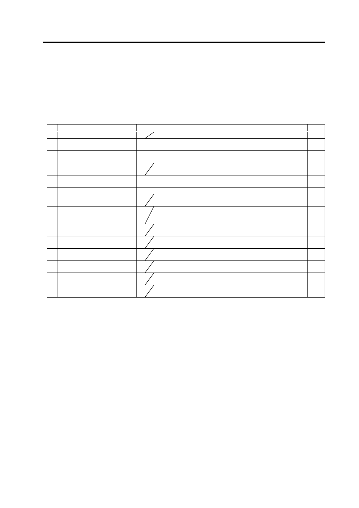
Drive unit alarm
No. Alar m name SV SP Alarm details Reset
11 Axis selection error
The axis No. selection switch setting is incorrect. AR
12 Memory error 1
A CPU or internal memory error was detected during the self-check at
power ON.
AR
13 Software processing error 1
§ §
The software process was not completed within the specified time.
(CPU1)
PR
14 Software processing error 2
{
The software process was not completed within the specified time.
(CPU2)
PR
16 Magnetic pole position detection
error
Creation of the initial magnetic pole, required for motor control, was not
completed.
PR
17 A/D converter error
An error was detected in the A/D converter for current FB detection. PR
18 Motor side detector, initial
communication error
Initial communication with the motor end detector was not possible. PR
19 Synchronous control/detector
communication error
§
Initial communication with the master axis motor end detector was not
possible when the closed current command synchronous control was
set. Or, the communication was cut off.
PR
1A Machine side detector, initial
communication error
Initial communication with the linear scale or ball screw end detector
was not possible.
PR
1B Machine side detector, CPU error 1
A CPU initial error was detected with the linear scale or ball screw end
detector.
PR
1C Machine side detector,
EEPROM/LED abnormality
§
An error was detected in the data stored in the memory with the linear
scale. Or, LED deterioration was detected with the linear scale.
PR
1D Machine side detector, data error
§
A data error was detected with the linear scale or ball screw end
detector.
PR
1E Machine side detector, memory
error
§
An internal memory error was detected with the linear scale. PR
1F Machine side detector,
communication error
§
An error was detected in the communication data with the linear scale
or ball screw end detector. Or, the communication was cut off.
PR
(Note 1) Motor stopping method applied when self-axis dr ive unit alarm occurs is indicated in SV for servo and in SP for spindle.
(Note 2) Servo (SV) alarm stopping method
{: Deceleration control (when SV048, SV055 or SV056 is set)
§: Dynamic brake stop
: Initial error (while motor is stopped)
(Note 3) Spindle (SP) alarm stopping method
{: Deceleration control (when SP038/bit0=1 is set)
§: Coast to a stop
: Initial error (while motor is stopped)
Resetting methods
NR : Reset with the NC RESET button. This alarm can also be reset with the PR and AR resetting conditions.
PR : Reset by turning the NC power ON again. This alarm can also be reset with the AR resetting conditions.
When the control axis is removed, this alarm can be reset with the NC RESET button. (Excluding alarms 32 and 37.)
AR : Reset by turning the servo drive unit power ON again.
6. Troubleshooting
6 - 5
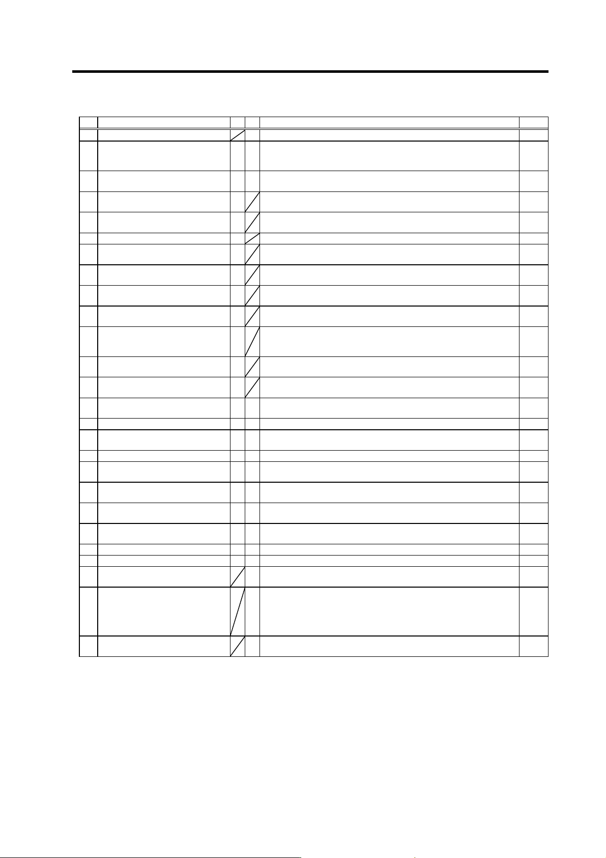
Drive unit alarm
No. Alar m name SV SP Alarm details Reset
20 Motor side detector, No signal 1
{
A PLG Z-phase no signal was detected. PR
21 Machine side detector, No signal 2
§
{
The pulse-type linear scale or ball screw end detector's ABZ-phase no
signal was detected with the servo, or the encoder no-signal was
detected with the spindle.
PR
23 Excessive speed deflection 1
§
A difference of 50r/min or more between the speed command and
speed feedback continued for longer than the set time.
PR
25 Absolute position lost
The backup voltage in the absolute position detector dropped causing
the absolute position to be lost.
AR
26 Unusable axis error
A power module error is occurring with the axis for which the axis No.
selection switch is set to "F" (not used axis).
PR
27 Machine side detector, CPU error 2
§
A CPU error was detected with the linear scale. PR
28 Machine side detector, overspeed
§
A speed exceeding the specified maximum speed was detected with
the linear scale.
PR
29 Machine side detector, absolute
position data error
§
An error was detected in the absolute position data detection circuit with
the linear scale.
PR
2A Machine side detector, incremental
position data error
§
An error was detected in the relative position data detection circuit with
the linear scale.
PR
2B Motor side detector, CPU error 1
A CPU initial error was detected with the motor end detector or linear
scale in the linear servo system.
PR
2C Motor side detector, EEPROM/LED
error
§
Deterioration of the LEDs was detected with the motor end detector. Or,
an error in the data stored in the memory was detected with the linear
scale in the linear servo system.
PR
2D Motor side detector, data error
§
A data error was detected with the motor end detector or linear scale in
the linear servo system.
PR
2F Motor side detector, communication
error
§
A communication data error was detected with the motor end detector
or linear scale for the linear servo. Or, communication was cut off.
PR
31 Overspeed
{
§
A rotation speed exceeding the motor's tolerable rotation speed was
detected.
PR
32 Power module overcurrent
§ §
The power module's overcurrent protection function activated. PR
34 Communication or CRC error
between NC and drive unit
{ {
An error was detected in the data received from the NC. PR
35 NC command error
{ {
The movement command data received from the NC was excessive. PR
36 Communication or transmission
error between NC and drive unit
{ {
Communication from the NC was cut off. PR
37 Initial parameter error
An illegal parameter was detected in the parameters received from the
NC at NC power ON.
PR
38 Communication or protocol error 1
between NC and drive unit
{ {
An error was detected in the communication frame received from the
NC.
PR
39 Communication or protocol error 2
between NC and drive unit
{ {
An error was detected in the axis information data received from the
NC.
PR
3A Overcurrent
§ §
An excessive current was detected in the motor drive current. PR
3B Power module overheat
§ §
The power module's temperature protection function activated. PR
3D Spindle speed lock
§
Even when the maximum torque was commanded, the motor speed
does not increase to 45r/min or more.
PR
3E Spindle speed overrun
§
1. A state in which the motor 's speed feedback exceeded the speed
command and accelerated was detected.
2. Even though the speed command is 0 (including when stopped
during position control), motor rotation exceeding the parameter
setting value was detected.
PR
3F Speed excessive deflection 2
§
During constant speed operation, the difference between the speed
command and speed feedback exceeded the set amount and set time.
PR
(Note 1) Motor stopping method applied when self-axis dr ive unit alarm occurs is indicated in SV for servo and in SP for spindle.
(Note 2) Servo (SV) alarm stopping method
{: Deceleration control (when SV048, SV055 or SV056 is set)
§: Dynamic brake stop
: Initial error (while motor is stopped)
(Note 3) Spindle (SP) alarm stopping method
{: Deceleration control (when SP038/bit0=1 is set)
§: Coast to a stop
: Initial error (while motor is stopped)
6. Troubleshooting
6 - 6
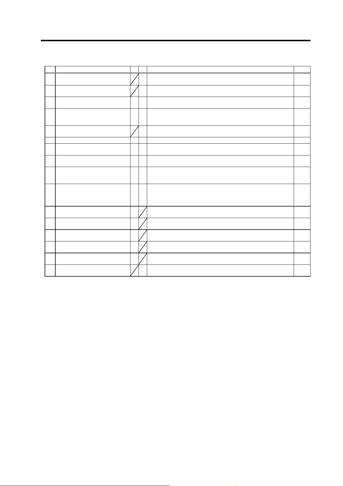
Drive unit alarm
No. Alar m name SV SP Alarm details Reset
40 Detector changeover unit,
changeover error
§
During 1-drive unit 2-motor control, an error was detected in the motor
changeover signal received form the detector changeover unit.
PR
41 Detector changeover unit,
communication error
§
During 1-drive unit 2-motor control, an error was detected in the
communication with the detector changeover unit.
PR
42 Feedback error 1
§ §
With the servo, pulse-type position detector feedback signal error was
detected. With the spindle, a PLG feedback signal error was detected.
PR
43 Feedback error 2
§ §
With the servo, an excessive error was detected in the position data for
the motor side detector and machine side detector. With the spindle, an
error was detected in the encoder feedback signal.
PR
44 C-axis changeover alarm
§
When using the coil changeover control motor, the mode was changed
to C-axis control while the high-speed coil was selected.
NR
46 Motor overheat
{ {
The temperature protection function in the motor or detector activated. NR
4E NC command mode error
§
A spindle control mode selection exceeding the specifications was
input.
NR
50 Overload 1
{
§
The overload detection level reached 100% or more. The motor or drive
unit is in the overload state.
NR
51 Overload 2
§ §
With the servo, a current command exceeding 95% of the unit's
maximum current continued for one second or more. With the spindle, a
load exceeding the continuous rating continued for 30 minutes or more.
NR
52 Excessive error 1
{ {
With the servo, the difference of the motor's actual position at servo ON
and the theoretical position exceeded the setting value. With the
spindle, the difference of the position command and position feedback
exceeded the setting value.
NR
53 Excessive error 2
§
The difference of the motor's actual position at servo OFF and the
theoretical position exceeded the setting value.
NR
54 Excessive error 3
{
The motor current was not detected when the excessive error 1 alarm
occurred.
NR
58 Collision detection 1 G0
{
When the collision detection function is valid, the disturbance torque
exceeded the collision detection value during rapid traverse (G0).
NR
59 Collision detection 1 G1
{
When the collision detection function is valid, the disturbance torque
exceeded the collision detection level during cutting feed (G1).
NR
5A Collision detection 2
{
When the collision detection function is valid, the command torque
reached the motor's maximum torque.
NR
5C Orientation feedback error
§
After orientation was completed, the command and feedback error
exceeded the parameter setting.
PR
(Note 1) Motor stopping method applied when self-axis dr ive unit alarm occurs is indicated in SV for servo and in SP for spindle.
(Note 2) Servo (SV) alarm stopping method
{: Deceleration control (when SV048, SV055 or SV056 is set)
§: Dynamic brake stop
: Initial error (while motor is stopped)
(Note 3) Spindle (SP) alarm stopping method
{: Deceleration control (when SP038/bit0=1 is set)
§: Coast to a stop
: Initial error (while motor is stopped)