bnp-b2365(eng)b.pdf - 第312页
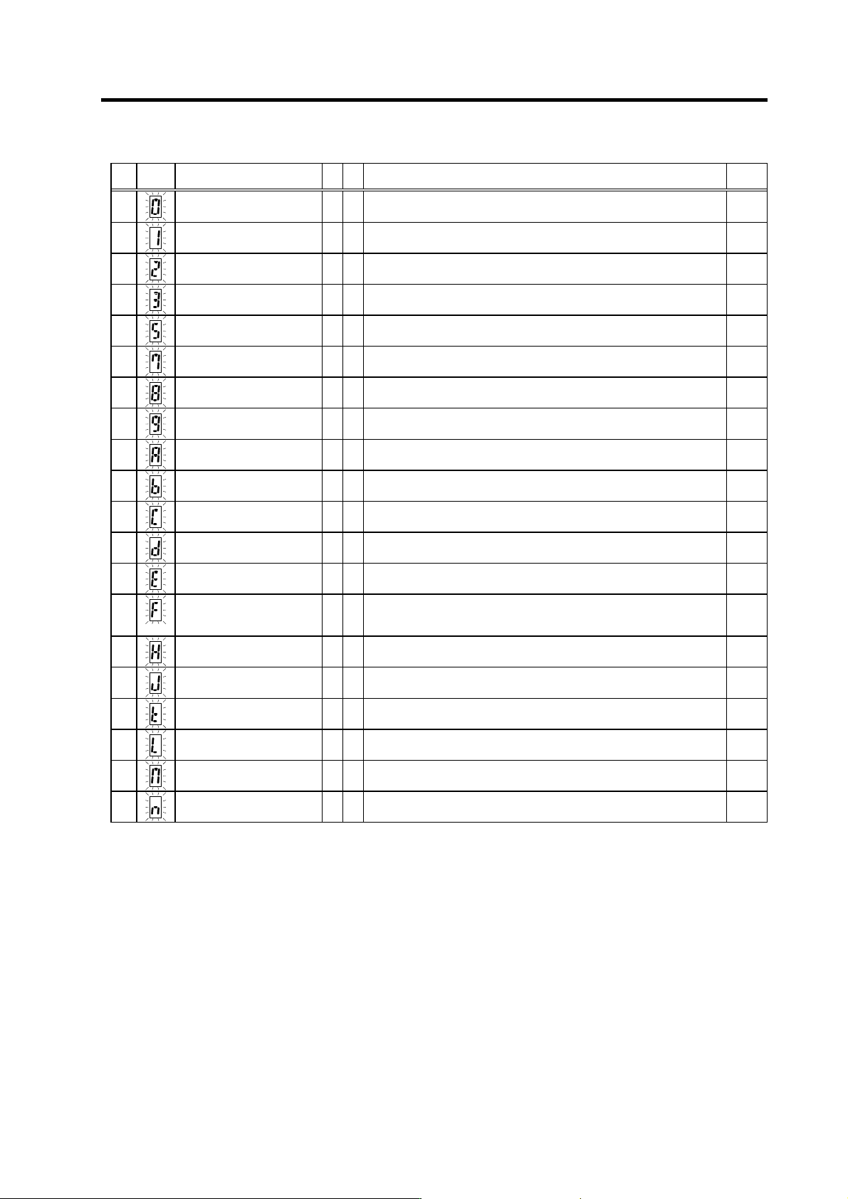
6. Troubleshooting 6 - 7 Power supply alarm No. LED display Alarm name CV CR Alarm details Reset 60 Instantaneous pow er failure § § A drop in the 24VDC po wer was detected. PR 61 Power module overcurrent § § The power m…
6. Troubleshooting
6 - 6
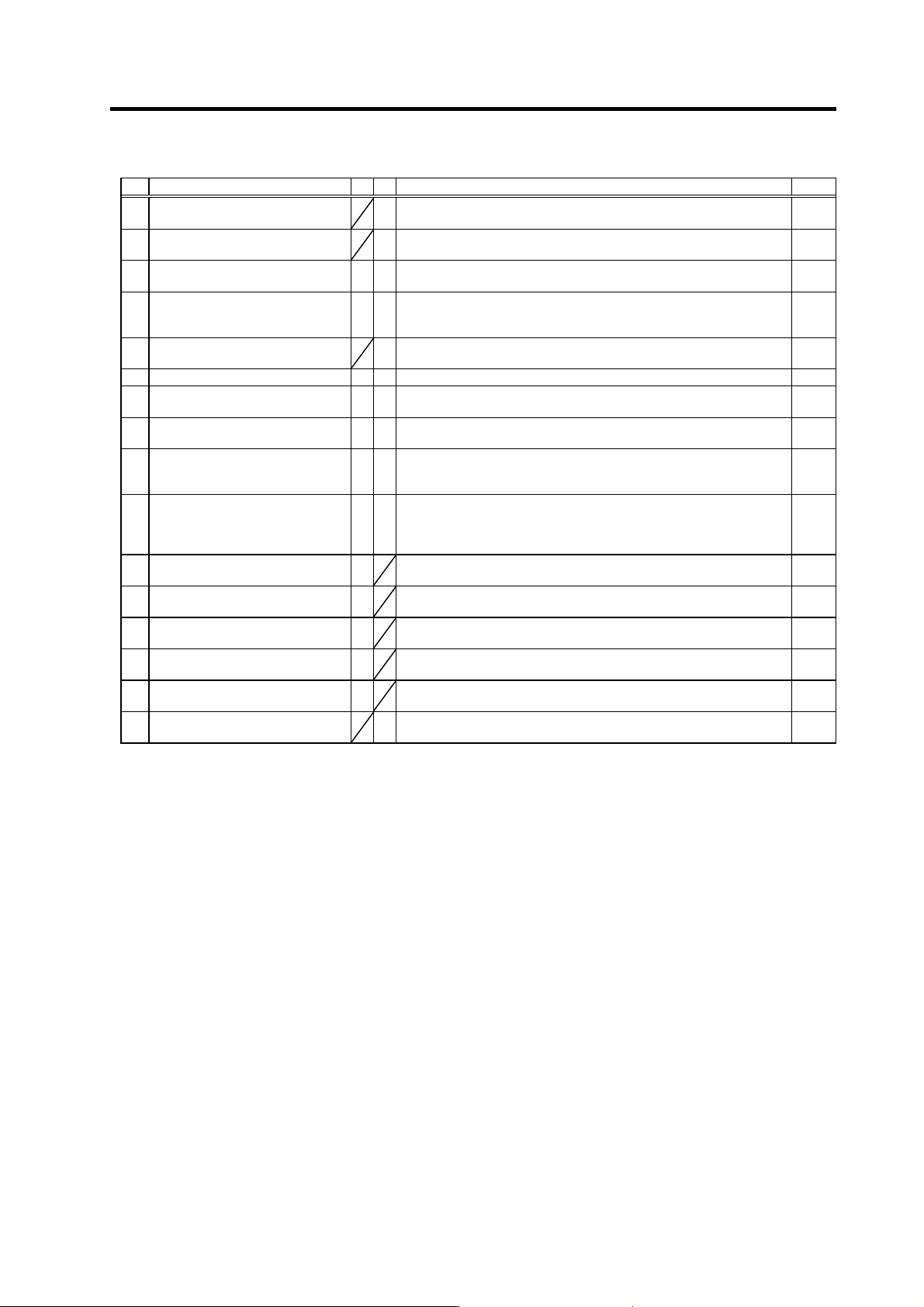
Drive unit alarm
No. Alar m name SV SP Alarm details Reset
40 Detector changeover unit,
changeover error
§
During 1-drive unit 2-motor control, an error was detected in the motor
changeover signal received form the detector changeover unit.
PR
41 Detector changeover unit,
communication error
§
During 1-drive unit 2-motor control, an error was detected in the
communication with the detector changeover unit.
PR
42 Feedback error 1
§ §
With the servo, pulse-type position detector feedback signal error was
detected. With the spindle, a PLG feedback signal error was detected.
PR
43 Feedback error 2
§ §
With the servo, an excessive error was detected in the position data for
the motor side detector and machine side detector. With the spindle, an
error was detected in the encoder feedback signal.
PR
44 C-axis changeover alarm
§
When using the coil changeover control motor, the mode was changed
to C-axis control while the high-speed coil was selected.
NR
46 Motor overheat
{ {
The temperature protection function in the motor or detector activated. NR
4E NC command mode error
§
A spindle control mode selection exceeding the specifications was
input.
NR
50 Overload 1
{
§
The overload detection level reached 100% or more. The motor or drive
unit is in the overload state.
NR
51 Overload 2
§ §
With the servo, a current command exceeding 95% of the unit's
maximum current continued for one second or more. With the spindle, a
load exceeding the continuous rating continued for 30 minutes or more.
NR
52 Excessive error 1
{ {
With the servo, the difference of the motor's actual position at servo ON
and the theoretical position exceeded the setting value. With the
spindle, the difference of the position command and position feedback
exceeded the setting value.
NR
53 Excessive error 2
§
The difference of the motor's actual position at servo OFF and the
theoretical position exceeded the setting value.
NR
54 Excessive error 3
{
The motor current was not detected when the excessive error 1 alarm
occurred.
NR
58 Collision detection 1 G0
{
When the collision detection function is valid, the disturbance torque
exceeded the collision detection value during rapid traverse (G0).
NR
59 Collision detection 1 G1
{
When the collision detection function is valid, the disturbance torque
exceeded the collision detection level during cutting feed (G1).
NR
5A Collision detection 2
{
When the collision detection function is valid, the command torque
reached the motor's maximum torque.
NR
5C Orientation feedback error
§
After orientation was completed, the command and feedback error
exceeded the parameter setting.
PR
(Note 1) Motor stopping method applied when self-axis dr ive unit alarm occurs is indicated in SV for servo and in SP for spindle.
(Note 2) Servo (SV) alarm stopping method
{: Deceleration control (when SV048, SV055 or SV056 is set)
§: Dynamic brake stop
: Initial error (while motor is stopped)
(Note 3) Spindle (SP) alarm stopping method
{: Deceleration control (when SP038/bit0=1 is set)
§: Coast to a stop
: Initial error (while motor is stopped)
6. Troubleshooting
6 - 7
Power supply alarm
No.
LED
display
Alarm name CV CR Alarm details Reset
60
Instantaneous power failure
§
§
A drop in the 24VDC power was detected. PR
61
Power module overcurrent
§
§
The power module's overcurrent protection function activated. PR
62
Frequency error
§
§
The input power frequency exceeded the specified range. PR
63
Auxiliary regeneration error
§
§
The auxiliary regenerative transistor is still ON. PR
65
Rush relay error
§
§
The rush resistance short-circuit relay does not turn ON. PR
67
Phase failure
§
§
There is a phase failure in the input power. PR
68
Watch dog
§
§
The system is not operating normally. AR
69
Ground fault
§
§
The motor power cable is contacting FG (ground). PR
6A
External contactor melting
§
§
The external contactor's contact has melted. PR
6B
Rush relay melted
§
§
The rush resistance short-circuit relay does not turn OFF. PR
6C
Main circuit error
§
§
An abnormality was detected in the main circuit capacitor's charging
operation.
PR
6D
Parameter error
§
§
The power supply unit's capacity is not appropriate for the regenerative
resistor type set with the parameters.
PR
6E
Memory error
§
§
An error was detected in the internal memory. AR
6F
Power supply error
§
§
The power supply is not connected, or an error was detected in the
power supply's A/D converter.
This is detected simultaneously if another power supply alarm occurs.
AR
71
Instantaneous power failure/
external emergency stop
§
§
An instantaneous power failure occurred. NR
73
Over-regeneration
§
§
The over-regeneration detection level exceeded 100%. The
regenerative resistor is in the overload state.
PR
74
Regenerative resistor
overheat
§
§
The temperature protection function in the regenerative resistor
activated.
PR
75
Overvoltage
§
§
The main circuit PN bus voltage exceeded the tolerable value. NR
76
External emergency stop
setting error
§
§
The rotary switch setting for the external emergency stop does not
match the parameter setting.
AR
77
Power module overheat
§
§
The power module's temperature protection function activated. AR
(Note 1) If a power supply alarm (60 to 77) occurs, all servos will stop with the dynamic brakes, and all spindles will be stop with the
coast to a stop.
(Note 2) "b", "C" and "d" displayed on the power supply unit's LED as a solid light (not flickering) do not indicate an alarm.
6. Troubleshooting
6 - 8
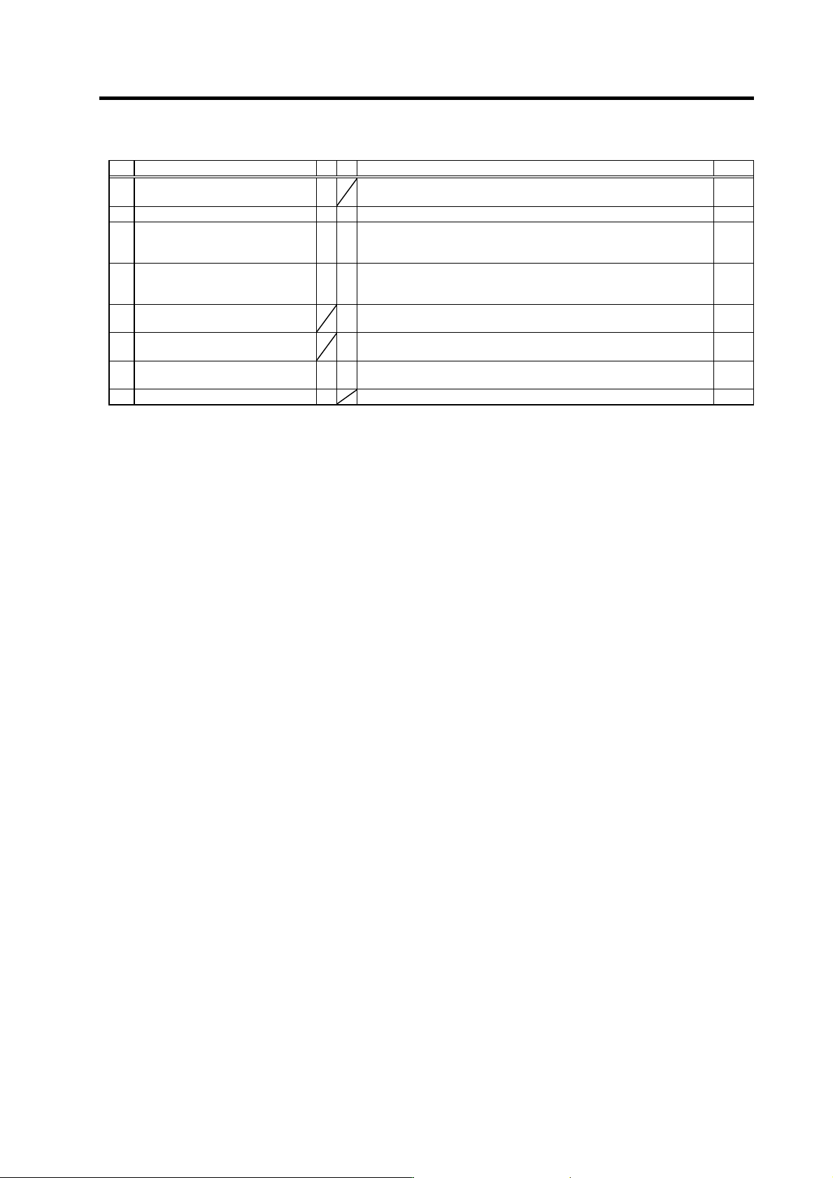
Drive unit alarm
No. Alar m name SV SP Alarm details Reset
7F Power reboot request
A mismatch in the program mode selection was detected. T urn the drive
unit power ON again.
PR
88 Watch dog
§ §
The system is not operating normally. AR
89 Detector converter unit 2
connection error
§ §
With the servo, an error was detected in the connection with the analog
output linear scale for the MDS-B-HR unit. With the spindle, initial
communication with the MDS-B-PJEX was not possible.
PR
8A Encoder converter unit 2
communication error
§ §
With the servo, an error was detected in the communication with the
serial output linear scale for the MDS-B-HR unit. With the spindle, an
error was detected in the communication with the MDS-B-PJEX.
PR
8B Encoder converter unit 2 automatic
adjustment error
§
An abnormal signal from the PLG was detected during automatic
adjustment of the PLG.
PR
8C Encoder converter unit 2 judgment
error
§
A detector type not within the specifications was detected with the
MDS-B-PJEX.
PR
8D Encoder converter unit 2 CPU error
§ §
With the servo, a CPU error was detected with the MDS-B-HR unit.
With the spindle, a CPU error was detected with the MDS-B-PJEX unit.
AR
8E Encoder converter unit 2 data error
§
A data error was detected with the MDS-B-HR unit. PR
(Note 1) Motor stopping method applied when self-axis dr ive unit alarm occurs is indicated in SV for servo and in SP for spindle.
(Note 2) Servo (SV) alarm stopping method
{: Deceleration control (when SV048, SV055 or SV056 is set)
§: Dynamic brake stop
: Initial error (while motor is stopped)
(Note 3) Spindle (SP) alarm stopping method
{: Deceleration control (when SP038/bit0=1 is set)
§: Coast to a stop
: Initial error (while motor is stopped)