bnp-b2365(eng)b.pdf - 第322页
6. Troubleshooting 6 - 17 Alarm No. 2B Motor side detector , CPU error 1 A CPU initial error was detected with the motor en d detector . Investigation det ails In vestigation results Remedies SV SP No abnormality is foun…
6. Troubleshooting
6 - 16
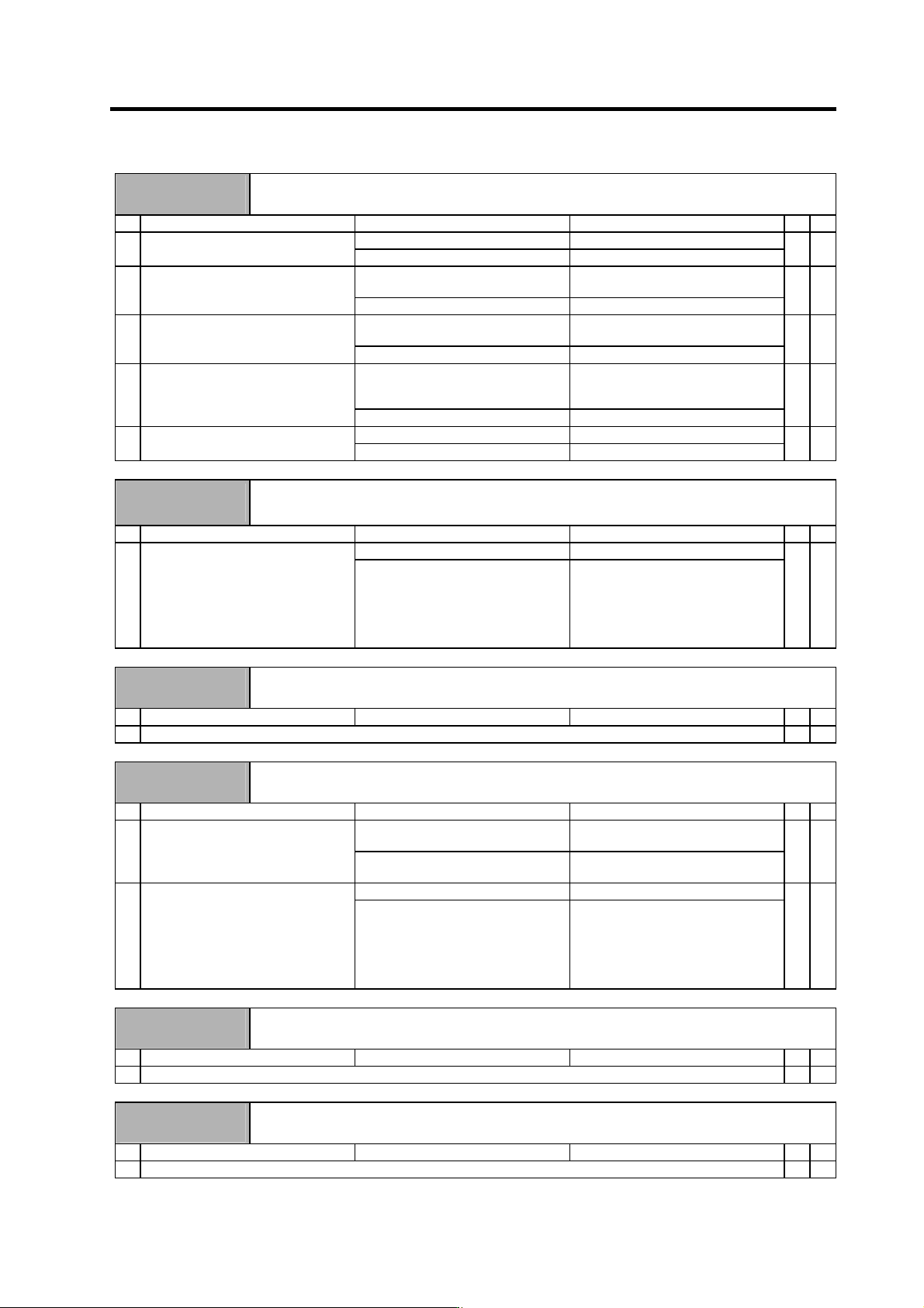
Alarm No.
25
Absolute position lost
The backup voltage in the absolute position detector dropped causing the absolute position to be lost.
Investigation details Investigation results Remedies SV SP
The warning is occurring. Investigate item 2. 1 Is warning 9F occurring at the same
time?
The warning is not occurring. Investigate item 3.
{
3V or less. Replace the battery, and establish the
zero point.
2 Measure the battery voltage with a
tester.
3V or more. Check the NC bus cable connection.
{
Alarm 18 occurred. Turn the drive unit control power ON
again, and establish the zero point.
3 Did alarm 18 occur when the power
was turned ON the last time?
Alarm 18 did not occur. Investigate item 4.
{
The unit was left for a long time.
Guide at delivery : 20 hours or more
After 5 years : 10 hours or more
Turn the drive unit control power ON
again, and establish the zero point.
4 Was the detector cable or battery
cable disconnected from the unit for a
long time?
The cables were not disconnected. Investigate item 5.
{
The connection is faulty. Replace the cable. 5 Check the detector cable or battery
cable connection with a tester.
The connection is normal. Replace the drive unit.
{
Alarm No.
26
Unusable axis error
A power module error is occurring with the axis for which the axis No. selection switch is set to "F" (not
used axis).
Investigation details Investigation results Remedies SV SP
No abnormality is found in particular. Replace the drive unit. 1 Check if there is any abnormality in
the unit's ambient environment.
(Ex. Ambient temperature, noise,
grounding)
An abnormality was found in the
ambient environment.
Take remedies according to the
causes of the abnormality.
Ex. High temperature:
Check the cooling fan.
Incomplete grounding:
Additionally ground.
{
Alarm No.
27
Machine side detector, CPU error 2
A CPU error was detected with the linear scale.
Investigation details Investigation results Remedies SV SP
1 Check the alarm No. "1B" items.
{
Alarm No.
28
Machine side detector, overspeed
A speed exceeding the specified maximum speed was detected with the linear scale.
Investigation details Investigation results Remedies SV SP
The rapid traverse rate is higher than
the specified value.
Use within the specified range. 1 Check the linear scale's maximum
speed.
The rapid traverse rate is less than
the specified value.
Investigate item 2.
{
No abnormality is found in particular. Replace the linear scale. 2 Check if there is any abnormality in
the detector's ambient environment.
(Ex. Ambient temperature, noise,
grounding)
An abnormality was found in the
ambient environment.
Take remedies according to the
causes of the abnormality.
Ex. High temperature:
Check the cooling fan.
Incomplete grounding:
Additionally ground.
{
Alarm No.
29
Machine side detector, absolute position data error
An error was detected in the absolute position data detection circuit with the linear scale.
Investigation details Investigation results Remedies SV SP
1 Check the alarm No. "1B" items.
{
Alarm No.
2A
Machine side detector, incremental position data error
An error was detected in the relative position data detection circuit with the linear scale.
Investigation details Investigation results Remedies SV SP
1 Check the alarm No. "1B" items.
{
6. Troubleshooting
6 - 17
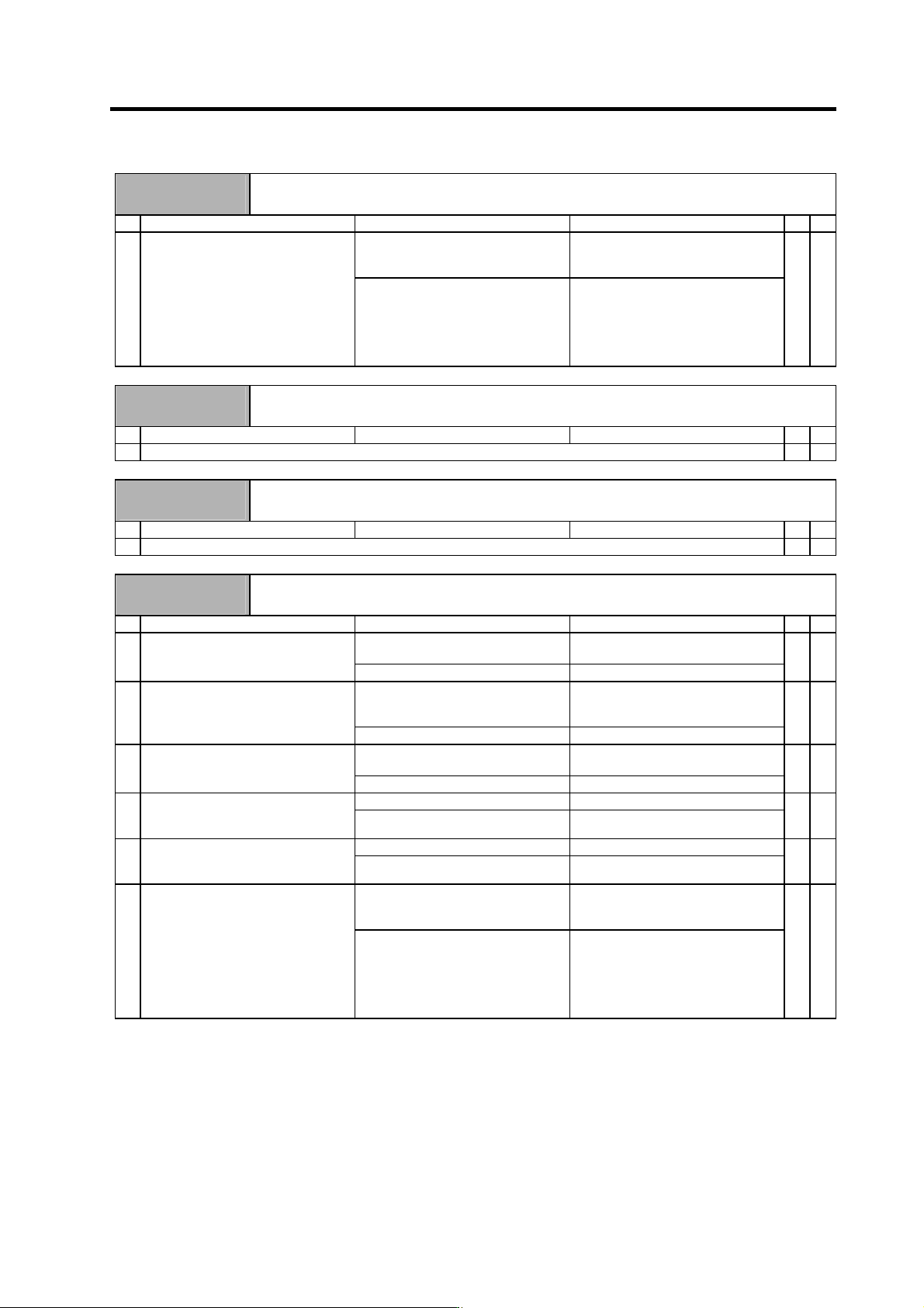
Alarm No.
2B
Motor side detector, CPU error 1
A CPU initial error was detected with the motor end detector.
Investigation details Investigation results Remedies SV SP
No abnormality is found in particular. Replace the detector.
(With the absolute position system,
the zero point must be established.)
1 Check if there is any abnormality in
the detector's ambient environment.
(Ex. Ambient temperature, noise,
grounding)
An abnormality was found in the
ambient environment.
Take remedies according to the
causes of the abnormality.
Ex. High temperature:
Check the cooling fan.
Incomplete grounding:
Additionally ground.
{
Alarm No.
2C
Motor side detector, EEPROM/LED error
Deterioration of the LEDs was detected with the m otor end detector.
Investigation details Investigation results Remedies SV SP
1 Check the alarm No. "2B" items.
{
Alarm No.
2D
Motor side detector, data error
A data error was detected with the motor end detector.
Investigation details Investigation results Remedies SV SP
1 Check the alarm No. "2B" items.
{
Alarm No.
2F
Motor side detector, communication error
A communication data error was detected with the motor end detector. Or, communication was cut off.
Investigation details Investigation results Remedies SV SP
The connector is disconnected (or
loose).
Correctly install. 1 Check whether the drive unit
connectors (CN2) or detector
connectors are disconnected.
The connector is not disconnected. Investigate item 2.
{
The cables are wired near each
other. (Noise is entering from the
power cable.)
Improve the cable wiring. 2 Is the detector cable wired in the
same conduit as the motor's power
cable or are the two cables laid in
parallel near each other?
The wires are sufficiently separated. Investigate item 3.
{
The motor FG wire is grounded on
the motor side.
Connect together on the drive unit
side.
3 Is the motor FG wire connected only
to the drive unit which drives it?
(Is the motor grounded to one point?)
The motor is grounded to one point. Investigate item 4.
{
There is a connection fault. Replace the detector cable. 4 Turn the power OFF, and check the
detector cable connection with a
tester. (Is the cable shielded?)
The connection is normal. Investigate item 5.
{
The alarm is on the drive unit side. Replace the drive unit. 5 Connect to another normal axis drive
unit, and check whether the fault is
on the drive unit side or detector side.
The alarm is on the detector side. Investigate item 6.
{
No abnormality is found in particular. Replace the detector.
(With the absolute position system,
the zero point must be established.)
6 Check if there is any abnormality in
the detector's ambient environment.
(Ex. Ambient temperature, noise,
grounding)
An abnormality was found in the
ambient environment.
Take remedies according to the
causes of the abnormality.
Ex. High temperature:
Check the cooling fan.
Incomplete grounding:
Additionally ground.
{
6. Troubleshooting
6 - 18
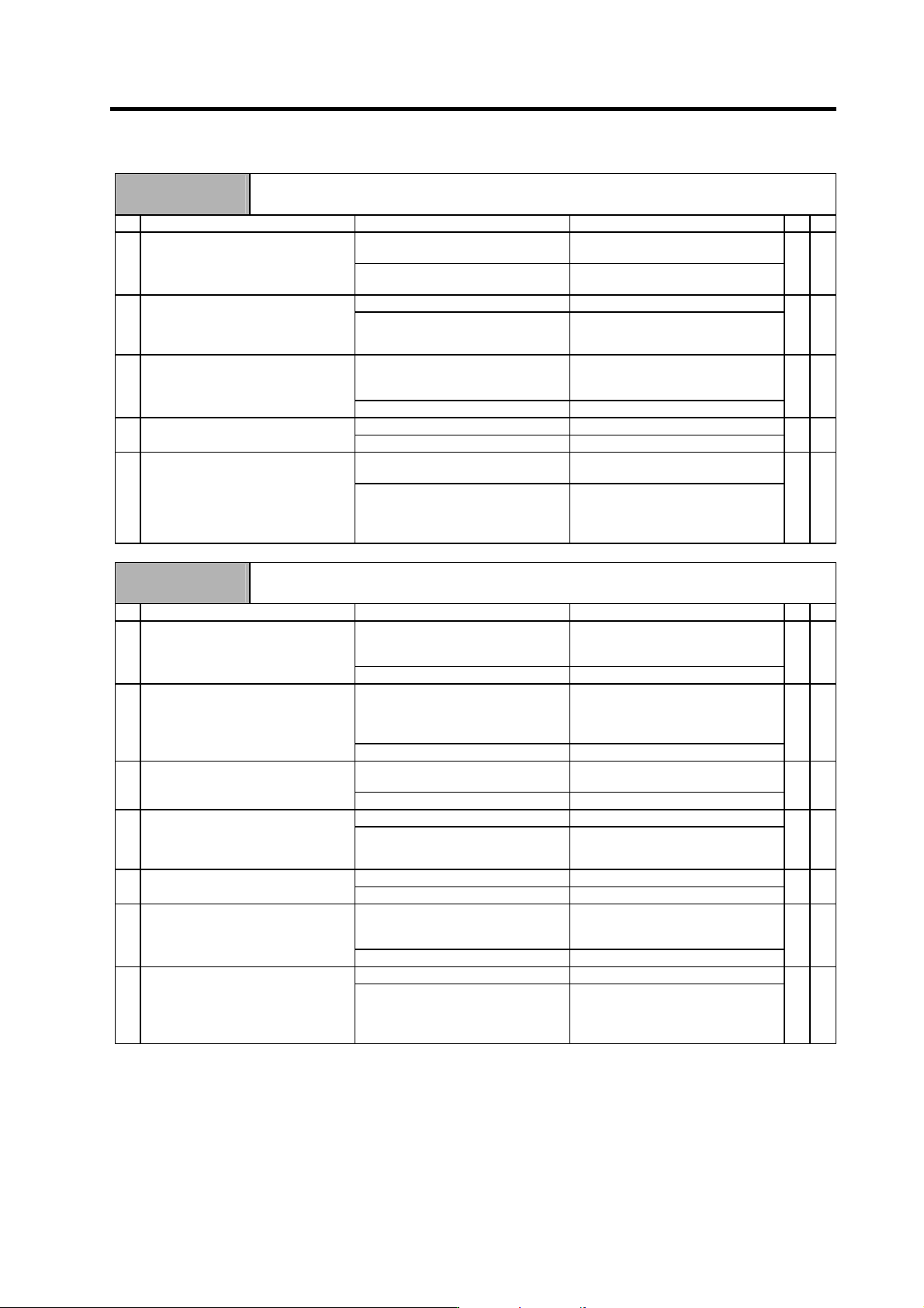
Alarm No.
31
Overspeed
A rotation speed exceeding the motor's tolerable rotation speed was detected.
Investigation details Investigation results Remedies SV SP
The rapid traverse rate is too fast. Set within the motor's maximum
rotation speed.
1 Check the rapid traverse rate (rapid)
and motor maximum rotation speed.
The speed is within the motor's
maximum rotation speed.
Investigate item 2.
{
The settings are incorrect. Correctly set. 2 Check the settings for the servo
parameters SV001 (PC1), SV002
(PC2), SV018 (PIT) and SV025
(MTYP).
Correctly set. Investigate item 5.
{
The setting is incorrect.
The alarm is detected at 115% of
SP017.
Correctly set. 3 Confirm the spindle parameter
SP017 (TSP) setting.
Correctly set. Investigate item 4.
{
There is a problem. Adjust the PLG output waveform. 4 Confirm the PLG output waveform.
Normal. Investigate item 5.
{
The waveform is overshooting. Increase the acceleration/
deceleration time constant.
5 Check whether the speed waveform
is overshooting.
The waveform is not overshooting. Check if there is any abnormality in
the unit's ambient environment.
(Ex.: Ambient temperature, noise,
grounding)
{ {
Alarm No.
32
Power module overcurrent
The power module's overcurrent protection function activated.
Investigation details Investigation results Remedies SV SP
The alarm occurs before READY ON.
(The drive unit is faulty.)
Check investigation item 2 and
following, and remove the cause of
the fault. Then replace the drive unit.
1 Check the repeatability.
The alarm occurs after READY ON. Investigate item 2.
{ {
The setting is incorrect.
Servo : SV025
Spindle : SP034, SP040, SP257 to
SP384
Correctly set.
2 Check the parameter setting.
• Motor type
The setting is correct. Investigate item 3.
{ {
The setting is large compared to the
standard value.
Set the standard value. 3 Check the parameter settings.
• Current loop gain
• Speed loop gain
The standard value is set. Investigate item 4.
{ {
The power cable is short-circuited. Replace the motor's power cable. 4 Disconnect the UVW phase wiring
from the terminal block, and the
cannon plug from the motor. Check
the insulation with a tester.
There is no problem. Investigate item 5.
{ {
The power cable is short-circuited. Replace the motor's power cable. 5 Check the insulation between the
motor power cable and FG.
There is no problem. Investigate item 6.
{ {
The motor is short-circuited. Replace the motor.
(With the absolute position system,
the zero point must be established.)
6 Connect the cannon plug, and check
the insulation between the power
cable and FG.
There is no problem. Investigate item 7.
{ {
No abnormality is found in particular. Replace the drive unit. 7 Check for any abnormalities in the
motor's ambient environment.
(Ex.: Ambient temperature, cutting
water)
An abnormality was found in the
ambient environment.
Replace the motor and improve the
motor installation environment.
(With the absolute position system,
the zero point must be established.)
{ {