bnp-b2365(eng)b.pdf - 第326页
6. Troubleshooting 6 - 21 Alarm No. 3B Power module overheat The power module's temperature protection function activated. Investigation det ails In vestigation results Remedies SV SP The fan is rotating, and an ala…
6. Troubleshooting
6 - 20
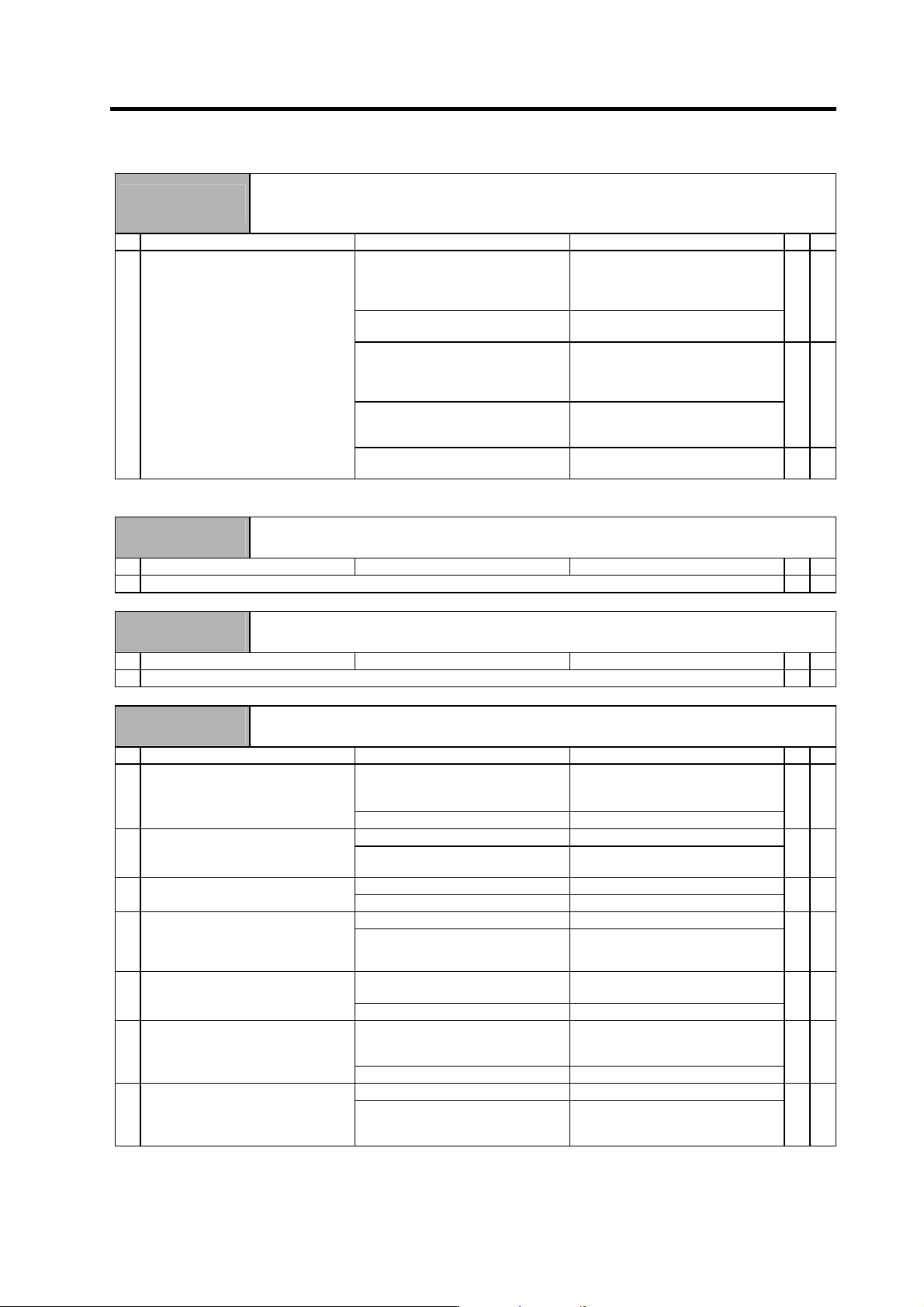
Alarm No.
37
Initial parameter error
An illegal parameter was detected in the parameters received from the NC at NC power ON.
"S02 initial parameter error ####" is displayed on the NC screen. #### indicates the incorrect
parameter No.
Investigation details Investigation results Remedies SV SP
SV001 to SV065 (M60S Series: 2201
to 2265)
SP001 to SP384 (M60S Series: 3201
to 3584)
Set the value within the designated
setting range.
1 Check the error parameter No.
SV101 (M60S Series: 2301)
The electronic gears are overflowing.
Check SV001, SV002 and SV018.
{ {
SV102 (M60S Series: 2302)
The absolute position detection
parameter is valid when OSE104 and
OSE105 are connected.
Absolute position control cannot be
used. To use, change to an absolute
position detector.
SV104 (M60S Series: 2304)
No SHG control operation is
provided.
SHG control cannot be used.
{
SV105 (M60S Series: 2305)
No adaptive filter option is provided.
The adaptive filter cannot be used.
{
(Note) Refer to "6-3-4 Parameter numbers at initial parameter error".
Alarm No.
38
Communication or protocol error 1 between NC and drive unit
An error was detected in the communication frame received from the NC.
Investigation details Investigation results Remedies SV SP
1 Check the alarm No. "34" items.
{ {
Alarm No.
39
Communication or protocol error 2 between NC and drive unit
An error was detected in the axis information data received from the NC.
Investigation details Investigation results Remedies SV SP
1 Check the alarm No. "34" items.
{ {
Alarm No.
3A
Overcurrent
An excessive current was detected in the motor drive current.
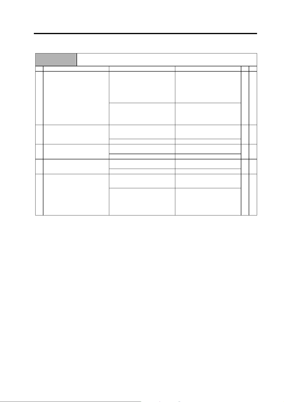
Investigation details Investigation results Remedies SV SP
Vibration is occurring.
• Set a filter.
• Lower the speed loop gain
(SV005).
1 Check whether vibration is occurring.
There is no vibration. Investigate item 2.
{
The setting is too large. Set an appropriate value. 2 The speed loop gain (SV005) setting
is larger than the standard value.
The setting is approximately the
same as the standard value.
Investigate item 3.
{
The setting is incorrect. Set the standard value. 3 Check the current loop gain.
(SV009, SV010, SV011, SV012)
The standard value is set. Investigate item 4.
{
The power cable is short-circuited. Replace the motor power cable. 4 Disconnect the UVW phase wiring
from the terminal block, and the
cannon plug from the motor. Check
the insulation with a tester.
There is no problem. Investigate item 5.
{
There is a ground fault at the power
cable.
Replace the motor power cable. 5 Check the insulation between the
motor power cable and FG.
There is no problem. Investigate item 6.
{
There is a ground fault in the motor. Replace the mot or.
(With the absolute position system,
the zero point must be established.)
6 Connect the cannon plug, and check
the insulation between the power
cable and FG.
There is no problem. Investigate item 7.
{
No abnormality is found in particular. Replace the drive unit. 7 Check if there is any abnormality in
the motor's ambient environment.
(Ex. Ambient temperature, cutting
water)
An abnormality was found in the
ambient environment.
Improve the installation environment.
(With the absolute position system,
the zero point must be established.)
{
6. Troubleshooting
6 - 21
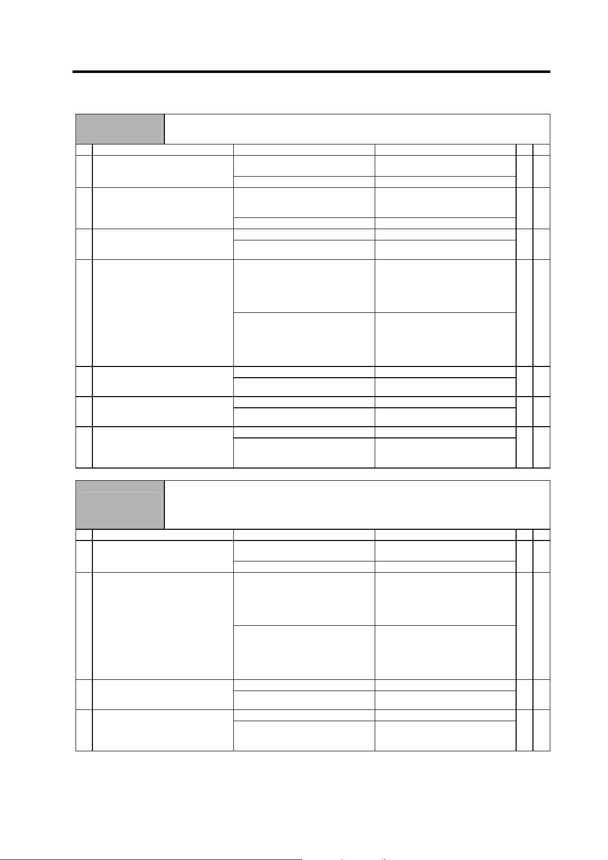
Alarm No.
3B
Power module overheat
The power module's temperature protection function activated.
Investigation details Investigation results Remedies SV SP
The fan is rotating, and an alarm did
not occur again.
Continue to use.
The power may be turned ON without
assuring more than 10 seconds for
the time from when the power is
turned OFF till when it is turned ON.
Leave for more than 10 seconds or
more, and turn the power ON again.
1 Turn the unit power ON again, and
confirm the rotation of the fan.
Note) Assure more than 10 seconds
for the time from when the
power is turned OFF till when it
is turned ON. For the fan used
for the drive unit, assuring
more than 10 seconds for the
time from when the power is
turned OFF till when it is turned
ON is required.
The fan did not rotate. Or, an alarm
occurred again.
Investigate item 2.
{ {
Large amounts of cutting oil or cutting
chips, etc., are adhered, or the
rotation is slow.
Clean or replace the fan. 2 Confirm adhesion of cutting oil or
cutting chips, etc. at the fan. Or check
if there is any abnormality such as
low rotation speed.
The fan is rotating properly. Investigate item 3.
{ {
Cutting oil or cutting chips, etc., are
adhered, and the fins are clogged.
Clean the fins. 3 Check whether the heat dissipating
fins are dirty.
The fins are normal. Investigate item 4.
{ {
55°C or more Improve the ventilation and cooling
for the power distribution panel.
4 Measure the drive unit's ambient
temperature.
Less than 55°C. Investigate item 5.
{ {
No abnormality is found in particular. If the alarm occurs even after the unit
temperature has dropped, replace
the unit.
5 Check if there is any abnormality in
the unit's ambient environment.
(Ex. Ambient temperature, noise,
grounding)
An abnormality was found in the
ambient environment.
Take remedies according to the
causes of the abnormality.
Ex. High temperature:
Check the cooling fan.
Incomplete grounding:
Additionally ground.
{ {
6. Troubleshooting
6 - 22
Alarm No.
3D
Spindle speed lock
Even when the maximum torque was commanded, the motor speed does not increase to 45r/min or
more.
Investigation details Investigation results Remedies SV SP
Occurs immediately after power is
turned ON.
Investigate item 2. 1 Does the alarm occur immediately
after the power is turned ON?
Occurs after normal operation. Investigate item 5.
{
There is abnormal noise. Investigate item 4.
(The initial pole estimate may be
incorrect.)
2 Is there any abnormal noise when
starting?
There is no abnormal noise. Investigate item 3.
{
The voltage is not supplied. Correctly supply the PN voltage. 3 Check that the PN voltage is supplied
to the drive unit.
• Is the CHARGE lamp ON?
Approx. 300V is correctly supplied. Investigate item 3.
{
The connections are incorrect. Connect correctly. 4 Check the motor power cable (U, V,
W phases). (Also check the operation
immediately after emergency stop is
cancelled.)
• The power cable is not connected.
• Is the cable connected to the motor
for another axis?
• Is the contactor between the drive
unit and motor OFF?
(When using coil changeover
specifications.)
The connections are correct. Investigate item 5.
{
The cutting load is large. Lower the cutting load. 5 Check the load value with the spindle
monitor, and investigate the
machine's load state.
The cutting load is not large. Investigate item 6.
{
Locked with a mechanical lock. Remove the cause of the lock. 6 Check whether the spindle rotary
section is locked with a mechanical
lock (C-axis clamp, etc.).
Not locked with a mechanical lock. Investigate item 7.
{
Improved. Replace the drive unit. 7 Try replacing the drive unit.
Not improved. Investigate the motor.
(Check the motor type and
parameters.)
{
Alarm No.
3E
Spindle speed overrun
1. A state in which the motor's speed feedback exceeded the speed command and accelerated was
detected.
2. Even though the speed command is 0 (including when stopped during position control), motor
rotation exceeding the parameter setting value was detected.
Investigation details Investigation results Remedies SV SP
Occurs immediately after power is
turned ON.
Investigate item 2. 1 Does the alarm occur immediately
after the power is turned ON?
Occurs after normal operation. Investigate item 3.
{
The connections are incorrect. Connect correctly. 2 Check the motor power cable (U, V,
W phases). (Also check the operation
immediately after emergency stop is
cancelled.)
• The power cable is not connected.
• Is the cable connected to the motor
for another axis?
• Is the contactor between the drive
unit and motor OFF?
(When using coil changeover
specifications.)
The connections are correct. Investigate item 3.
{
Locked with a mechanical lock. Remove the cause of the lock. 3 Check whether the spindle rotary
section is locked with a mechanical
lock (C-axis clamp, etc.).
Not locked with a mechanical lock. Investigate item 4.
{
Improved. Replace the drive unit. 4 Try replacing the drive unit.
Not improved. Investigate the motor.
(Check the motor type and
parameters.)
{