bnp-b2365(eng)b.pdf - 第332页
6. Troubleshooting 6 - 27 Alarm No. 51 Overload 2 With the servo, a current command exceeding 95% of the unit's maximum current co ntinued for one second or more. With the spindle, a load exceeding the continuous ra…
6. Troubleshooting
6 - 26
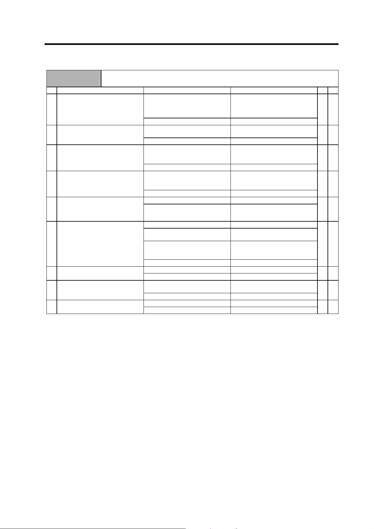
Alarm No.
50
Overload 1
The overload detection level reached 100% or more. The motor or drive unit is in the overload state.
Investigation details Investigation results Remedies SV SP
The standard values (below) are not
set.
Servo : SV021 = 60, SV022 = 150
Spindle : SV063 = 60, SP064 = 110
Set the standard values.
1 Check the overload parameters.
Servo : SV021, SV022
Spindle : SP063, SP064
The standard values are set. Investigate item 2.
{ {
The load is large. Servo : Investigate item 3.
Spindle : Investigate item 7.
2 Check the overload % (servo) or load
meter (spindle).
The load is not large. Investigate item 9.
{ {
Resonance is occurring. Adjust the parameters.
• Set the notch filter.
• Lower VGN1 (SV005).
3 Check whether machine resonance is
occurring.
Resonance is not occurring. Investigate item 4.
{
The motor is hunting. Adjust the parameters.
• Increase VGN1 (SV005).
• Lower VIA (SV008).
4 Check whether the shaft sways when
the motor is stopped. (Hunting)
The motor is not hunting. Investigate item 5.
{
The motor brakes are not released. Correct the faulty section. 5 Check the brake operation
Check the brake relay.
Check the connector (CN20)
connection.
The motor brake operation is normal. Investigate item 6.
{
The cutting load is large. Lower the cutting load.
There is interference with the
positioning pin.
When using the positioning pin, turn
the servo OFF when stopped.
An excessive force is applied from
the machine.
Check whether the ball screw is bent,
or whether there is a fault in the
guide.
6 Check the load current with the NC
Servo Monitor, and investigate the
machine load.
The machine load is not large. Investigate item 8.
{
There is a problem. Adjust the PLG output waveform. 7 Check the PLG output waveform.
Normal Investigate item 8.
{
The motor performance is
insufficient.
Lower the acceleration/deceleration
rate or cutting load.
8 Confirm the motor capacity selection
again.
The motor performance is sufficient. Investigate item 9.
{ {
Improved. Replace the drive unit. 9 Try replacing the drive unit.
Not improved. Replace the motor.
{ {
(Note) NR and PR resetting are not possible when the overload level is 50% or more. Do not forcibly reset (AR) by turning the unit
power OFF. If AR resetting is used at 50% or higher, the level is set to 80% when the power is turned ON next. (Servo)
6. Troubleshooting
6 - 27
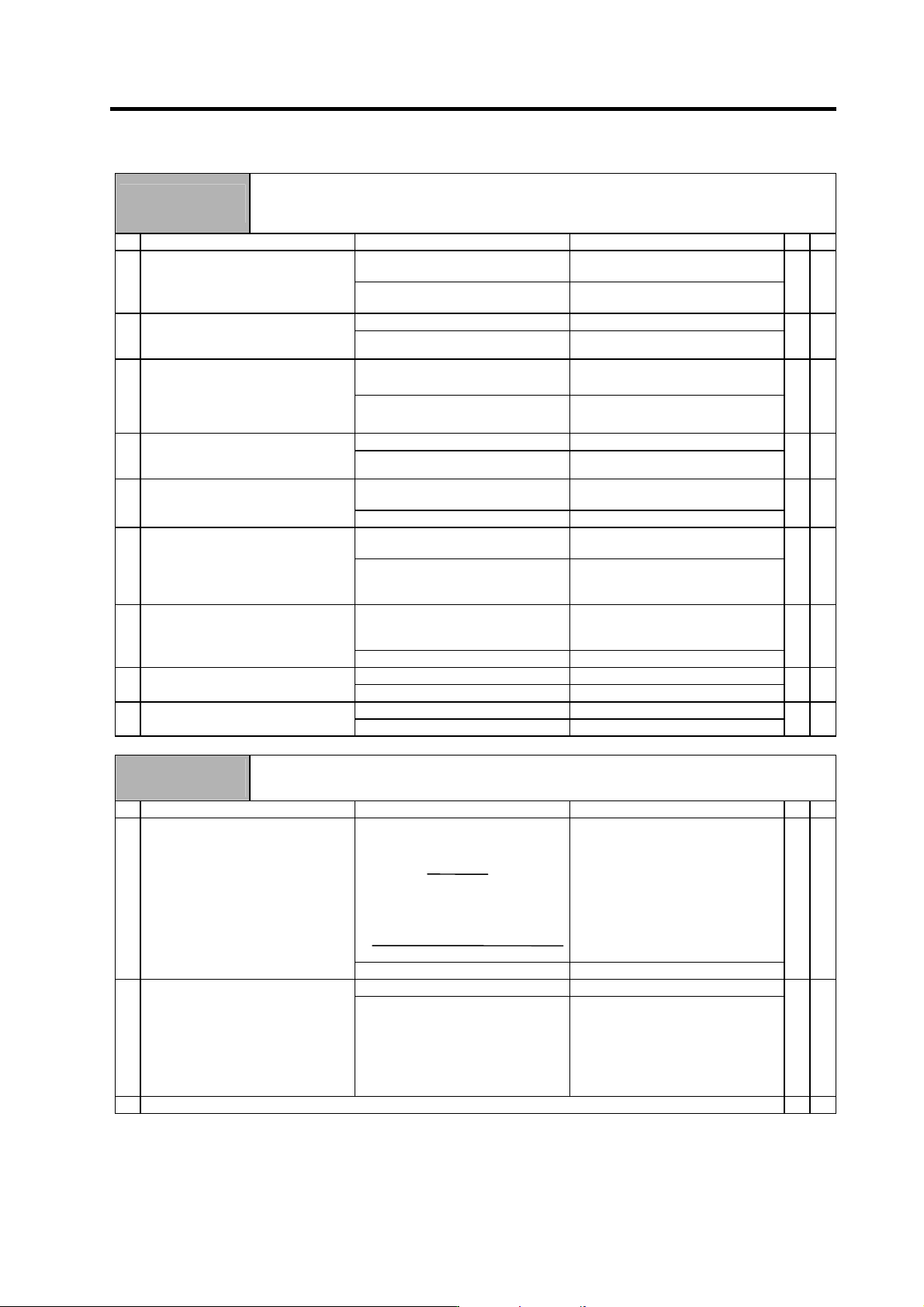
Alarm No.
51
Overload 2
With the servo, a current command exceeding 95% of the unit's maximum current continued for one
second or more. With the spindle, a load exceeding the continuous rating continued for 30 minutes or
more.
Investigation details Investigation results Remedies SV SP
The alarm occurred after ready ON
before operation starts.
Investigate item 2. 1 Did the alarm occur immediately after
READY ON?
The alarm occurred after normal
operation.
Investigate item 5.
{
The voltage is not supplied. Correctly supply the PN voltage. 2 Check that the PN voltage is supplied
to the drive unit.
Is the CHARGE lamp ON?
Approx. 300V is correctly supplied. Investigate item 3.
{
The connections are incorrect. Connect correctly. 3 Check the motor power cable (U, V,
W phases).
The power cable is not connected.
Is the cable connected to the motor
for another axis?
The connections are correct. Investigate item 4.
{
The connections are incorrect. Connect correctly. 4 Check the detector cable connection.
Is the cable connected to the motor
for another axis?
The connections are correct. Investigate item 5.
{
The machine has collided. Check the machining program and
soft limit settings.
5 Check whether the machine has
collided.
The machine has not collided. Investigate item 6.
{
The current is saturated during
acceleration/deceleration.
Increase the acceleration/
deceleration time constant.
6 Check whether the current value on
the NC Servo Monitor screen is
saturated during
acceleration/deceleration.
The current value during
acceleration/deceleration is
appropriate.
Investigate item 7.
{
The FB signal is abnormal. Replace the detector.
(With the absolute position system,
the zero point must be established.)
7 Check the detector FB.
The FB signal is normal. Replace the drive unit.
{
The load is large. Lower the load. 8 Check the load meter value.
The load is not large. Investigate item 9.
{
There is a problem. Adjust the PLG output waveform. 9 Check the PLG output waveform.
Normal Replace the drive unit.
{
Alarm No.
52
Excessive error 1
The difference between the motor's actual position at servo ON and the theoretical position exceeded
the setting value.
Investigation details Investigation results Remedies SV SP
The excessive error detection width is
too small.
Servo standard value:
SV023 =
RAPID
60
×
PGN1
÷ 2
For the spindle, a value larger than
the droop amount:
Droop amount =
Spindle rotation speed
×
No. of pulses
60
×
position loop gain
Set appropriate values. 1 Check the excessive error detection
width.
SV023 (Servo)
SP102 (Orientation control)
SP154, SP155 (C-axis control)
SP177/bitD, SP186 (Spindle
synchronous control)
SP193/bitD, SP218 (Synchronous
tap)
Appropriate values are set. Investigate item 2.
{ {
The polarity is reversed. Correctly set the parameters. 2 Check the position detector polarity.
SV017/bit4 (Servo)
SP097/bit5 (Orientation control)
SP129/bit5 (C-axis control)
SP177/bit5 (Spindle synchronous
control)
SP193/bit5 (Synchronous tap
control)
Normal. Investigate item 3.
{ {
3 Check the alarm No. "51" items.
{ {
6. Troubleshooting
6 - 28
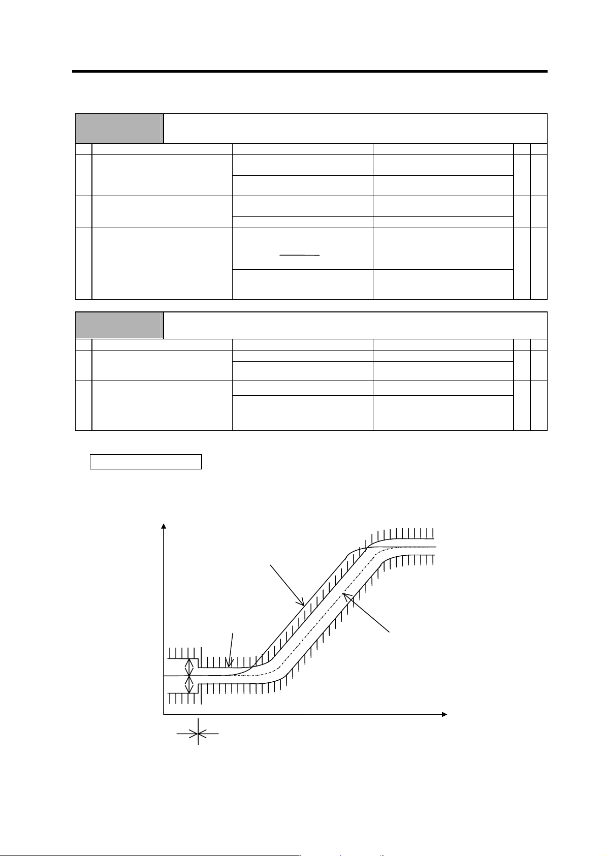
Alarm No.
53
Excessive error 2
The difference between the motor's actual position at servo OFF and the theoretical position exceeded
the setting value.
Investigation details Investigation results Remedies SV SP
NC parameter (M60S Series) #1064
svof = 0
Investigate item 2. 1 Check the follow-up function while
the NC is in the servo OFF state.
NC parameter (M60S Series) #1064
svof = 1
Investigate item 3.
{
The axis moved. Adjust the brakes, etc., so that the
axis does not move.
2 Check whether the axis has moved
during servo OFF, and check the
motor brake operation.
The axis has not moved. Investigate item 3.
{
The excessive error detection width is
too small.
SV026 =
RAPID
60
×
PGN1
÷ 2
Set an appropriate value.
3 Check the excessive error detection
width.
SV026 (Servo)
An appropriate value is set. Check for problems on the NC side,
such as the position FB follow-up
control.
{
Alarm No.
54
Excessive error 3
The motor current was not detected when the excessive error 1 alarm occurred.
Investigation details Investigation results Remedies SV SP
The voltage is not supplied. Correctly supply the PN voltage. 1 Check that the PN voltage is supplied
to the drive unit.
• Is the CHARGE lamp ON?
Approx. 300V is correctly supplied. Investigate item 2.
{
The connections are incorrect. Connect correctly. 2 Check the motor power cable (U, V,
W phases).
• The power cable is not connected.
• Is the cable connected to the motor
for another axis?
The connections are correct. Replace the drive unit.
{
Supplement (servo)
Depending on the ideal machine position in respect to the command position, the actual machine
position could enter the actual shaded section shown below, which is separated more than the
distance set in OD1.
Ideal machine position
Servo OFF
Command position
Servo ON
Time
OD1
OD1
OD2
OD2
Position