bnp-b2365(eng)b.pdf - 第334页
6. Troubleshooting 6 - 29 Alarm No. 58 Collision detection 1 G0 When the collision detection function is valid, t he disturbance torque exceeded the collision detection value during rapid traverse (G0). Investigation det…
6. Troubleshooting
6 - 28
Alarm No.
53
Excessive error 2
The difference between the motor's actual position at servo OFF and the theoretical position exceeded
the setting value.
Investigation details Investigation results Remedies SV SP
NC parameter (M60S Series) #1064
svof = 0
Investigate item 2. 1 Check the follow-up function while
the NC is in the servo OFF state.
NC parameter (M60S Series) #1064
svof = 1
Investigate item 3.
{
The axis moved. Adjust the brakes, etc., so that the
axis does not move.
2 Check whether the axis has moved
during servo OFF, and check the
motor brake operation.
The axis has not moved. Investigate item 3.
{
The excessive error detection width is
too small.
SV026 =
RAPID
60
×
PGN1
÷ 2
Set an appropriate value.
3 Check the excessive error detection
width.
SV026 (Servo)
An appropriate value is set. Check for problems on the NC side,
such as the position FB follow-up
control.
{
Alarm No.
54
Excessive error 3
The motor current was not detected when the excessive error 1 alarm occurred.
Investigation details Investigation results Remedies SV SP
The voltage is not supplied. Correctly supply the PN voltage. 1 Check that the PN voltage is supplied
to the drive unit.
• Is the CHARGE lamp ON?
Approx. 300V is correctly supplied. Investigate item 2.
{
The connections are incorrect. Connect correctly. 2 Check the motor power cable (U, V,
W phases).
• The power cable is not connected.
• Is the cable connected to the motor
for another axis?
The connections are correct. Replace the drive unit.
{
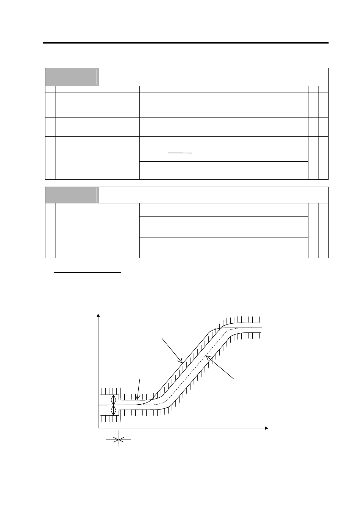
Supplement (servo)
Depending on the ideal machine position in respect to the command position, the actual machine
position could enter the actual shaded section shown below, which is separated more than the
distance set in OD1.
Ideal machine position
Servo OFF
Command position
Servo ON
Time
OD1
OD1
OD2
OD2
Position
6. Troubleshooting
6 - 29
Alarm No.
58
Collision detection 1 G0
When the collision detection function is valid, the disturbance torque exceeded the collision detection
value during rapid traverse (G0).
Investigation details Investigation results Remedies SV SP
The machine has collided. Check the machining program and
soft limit settings.
1 Check whether the machine has
collided.
The machine has not collided. Increase the detection level (SV060).
(The detection level should have an
allowance and be set as approx.
1.5-times the maximum disturbance
torque.)
{
Alarm No.
59
Collision detection 1 G1
When the collision detection function is valid, the disturbance torque exceeded the collision detection
level during cutting feed (G1).
Investigation details Investigation results Remedies SV SP
The machine has collided. Check the machining program and
soft limit settings.
1 Check whether the machine has
collided.
The machine has not collided. Increase the detection level (SV035.
clG1).
(Set the detection level larger than
the maximum cutting load.)
{
Alarm No.
5A
Collision detection 2
When the collision detection function is valid, the command torque reached the motor's maximum
torque.
Investigation details Investigation results Remedies SV SP
The machine has collided. Check the machining program and
soft limit settings.
1 Check whether the machine has
collided.
The machine has not collided. Investigate item 2.
{
The current is saturated during
acceleration/deceleration.
Investigate item 3. 2 Check whether the current value on
the NC Servo Monitor screen is
saturated during
acceleration/deceleration.
The current value during
acceleration/deceleration is
appropriate.
Investigate the cause of the load
fluctuation.
{
The constant can be changed. Increase the acceleration/
deceleration time constant.
3 Can the acceleration/deceleration
time constant be changed?
The constant cannot be changed. Set to ignore collision detection
method 2.
{
Alarm No.
5C
Orientation feedback error
After orientation was completed, the command and feedback error exceeded the parameter setting.
Investigation details Investigation results Remedies SV SP
The cable is not correctly shielded. Shield the cable. 1 Check the PLG cable shield.
The cable is correctly shielded. Investigate item 2.
{
The cable is incorrectly connected or
broken.
Replace the cable. 2 Check the PLG cable connection.
Normal Investigate item 3.
{
There is a problem. Adjust the PLG output waveform. 3 Check the PLG output waveform.
Normal Replace the drive unit
{
6. Troubleshooting
6 - 30
Alarm No.
60
Instantaneous power failure
A drop in the 24VDC power was detected.
Investigation details Investigation results Remedies
CV CR
The voltage is not applied. Investigate item 3.
The voltage is 20.4VDC or less. Increase the power voltage.
The voltage drops below 20.4VDC
sometimes.
Investigate item 4.
1 Is 24VDC applied on the CN22
connector?
Is the voltage low, or does it drop
sometimes?
The voltage is correctly applied. Investigate item 2.
{
The LEDs are not ON. Replace the unit. 2 Are the LEDs on the CR unit ON?
The LEDs are ON. Investigate item 4.
{
The power is abnormal. Replace the power. 3 Check the wiring and power voltage.
The wiring or connectors are
abnormal.
Replace the cable.
{
A voltage drop is not observed. Check the wiring. 4 Check whether the voltage is
dropping because of another load.
A voltage drop is observed. Increase the power capacity.
{
Alarm No.
61
Power module overcurrent
The power module's overcurrent protection function activated.
Investigation details Investigation results Remedies
CV CR
The alarm occurs immediately after
200VAC is supplied and after READY
is turned ON.
Replace the unit.
The alarm occurs frequently during
READY ON.
Investigate item 3.
1 Check the state of the operation
when the alarm occurs, and check
the repeatability.
The alarm occurs after continuous
operation for a long time.
The unit is hot.
Investigate item 2.
{
The total load of all motors exceeds
the rated capacity of the power
supply unit.
Lower the motor load and operation
frequency.
2 Check the load state of all motors,
and the starting/stopping frequency.
The total does not exceed the
capacity.
Investigate item 3.
{
The power capacity is insufficient. Increase the power capacity. 3 Check the power capacity.
The specified power capacity is
secured.
Investigate item 4.
{
The voltage drops to 170V or less
occasionally.
Increase the power capacity.
The difference of the voltage across
wires is 10V or more.
Improve the power phase balance.
4 Measure the voltage across wires.
• Is the voltage 170V or more even
when the motor is accelerating?
The difference of the voltage across
wires is less than 10V.
Investigate item 5.
{
The power voltage is distorted. Improve the source of the distortion.
Install an AC reactor.
5 Measure the power voltage with a
synchroscope, and check whether
there is any distortion.
• Are there any other devices
causing the power distortion?
The power voltage waveform is not
abnormal.
Investigate item 6.
{
No abnormality is found in particular. Replace the unit. 6 Check if there is any abnormality in
the unit's ambient environment.
(Ex. Noise, grounding)
The grounding is incomplete.
An alarm will occur easily if another
device operates.
Take remedies according to the
causes of the abnormality.
Ex. Incomplete grounding:
Additionally ground.
Noise: Noise measures for
other devices.
{