bnp-b2365(eng)b.pdf - 第353页
7. Maintenance 7 - 1 7-1 Insp ections ............................................................................................................... ......................... 7-2 7-2 Servic e parts .....................…
6. Troubleshooting
6 - 47
[7] The spindle coasts during decelerati on.
Investigation item Investigation results Remedies
There is slipping. Repair the machine side.
1
Check whether there is slipping between
the motor and spindle. (When connected
with a belt or clutch.)
No particular problems found. Replace the drive unit.
[8] The rotation does not stabilize.
Investigation item Investigation results Remedies
The rotation stabilizes when the settings
values are both set to approx. double.
Change the setting value.
Note that the gear noise may
increase.
1
Check the spindle parameter settings.
(SP022, SP023)
The symptoms do not change even
when the above value is set.
Return the setting values to the
original values.
Investigate investigation item 2 and
remedy.
The connector is disconnected (or
loose).
Correctly connect the connector.
2
Tug on the connector by hand to check
whether the speed detector connector
(spindle drive unit side and speed
detector side) is loose.
The connector is not disconnected (or
loose).
Investigate investigation item 3 and
remedy.
The connection is faulty or
disconnected.
Replace the detector cable.
Correct the connection.
3
Turn the power OFF, and check the
connection of the speed detector cable
with a tester.
(Especially check the shield wiring.)
The connection is normal.
Investigate investigation item 4 and
remedy.
The grounding is incomplete. Correctly ground.
The alarm occurs easily when a specific
device operates.
Use noise measures on the device
described on the left.
4
Investigate the wiring and installation
environment.
• Is the ground correctly connected?
• Are there any no ise-gener ating devices
near the drive unit?
No particular problems found. Replace the drive unit.
[9] The speed does not rise abov e a set level.
Investigation item Investigation results Remedies
The speed command is not input
correctly.
Input the correct speed command.
1
Check the speed command.
Check whether the override input is input
from the machine operation panel.
The speed command is input correctly.
Investigate investigation item 2 and
remedy.
The load has become heavier. Repair the machine side.
2
Check whether the load has suddenly
become heavier.
No particular problems found.
Investigate investigation item 3 and
remedy.
The bearings do not rotate smoothly. Replace the spindle motor.
3
Manually rotate the motor bearings and
check the movement.
The bearings rotate smoothly.
Investigate investigation item 4 and
remedy.
The connector is disconnected (or
loose).
Correctly connect the connector.
4
Tug on the connector by hand to check
whether the speed detector connector
(spindle drive unit side and speed
detector side) is loose.
The connector is not disconnected (or
loose).
Investigate investigation item 5 and
remedy.
The connection is faulty or
disconnected.
Replace the detector cable.
Correct the connection.
5
Turn the power OFF, and check the
connection of the speed detector cable
with a tester.
(Especially check the shield wiring.)
The waveform is normal. Replace the spindle drive unit.

7. Maintenance
7 - 1
7-1 Inspections........................................................................................................................................ 7-2
7-2 Service parts..................................................................................................................................... 7-2
7-3 Adding and replacing units and parts ............................................................................................... 7-3
7-3-1 Replacing the drive unit ............................................................................................................. 7-3
7-3-2 Replacing the unit fan ................................................................................................................ 7-4
7. Maintenance
7 - 2
WARNING
1. Before starting maintenance or inspections, turn the main circuit power and
control power both OFF. Wait at least ten minutes for the CHARGE lamp to
turn OFF, and then using a tester, confirm that the input and output voltage
are zero. Failure to observe this could lead to electric shocks.
2. Inspections must be carried out by a qualified technician. Failure to observ e
this could lead to electric shocks. Contact your nearest Mitsubishi branch or
dealer for repairs and part replacement.
CAUTION
1. Never perform a megger test (measure the insulation resistance) of the
servo drive unit. Failure to observe this could lead to faults.
2. The user must never disassemble or modify this product.
7-1 Inspections
Periodic inspection of the following items is recommended.
[1] Are any of the screws on the terminal block loose? If loose, tighten them.
[2] Is any abnormal noise heard from the servomotor bearings or brake section?
[3] Are any of the cables damaged or cracked? If the cables move with the machine, periodically
inspect the cables according to the working conditions.
[4] Is the core of the load coupling shaft deviated?
7-2 Service parts
A guide to the part replacement cycle is shown below. Note that these will differ according to the
working conditions or environmental conditions, so replace the parts if any abnormality is found.
Contact Mitsubishi branch or your dealer for repairs or part replacements.
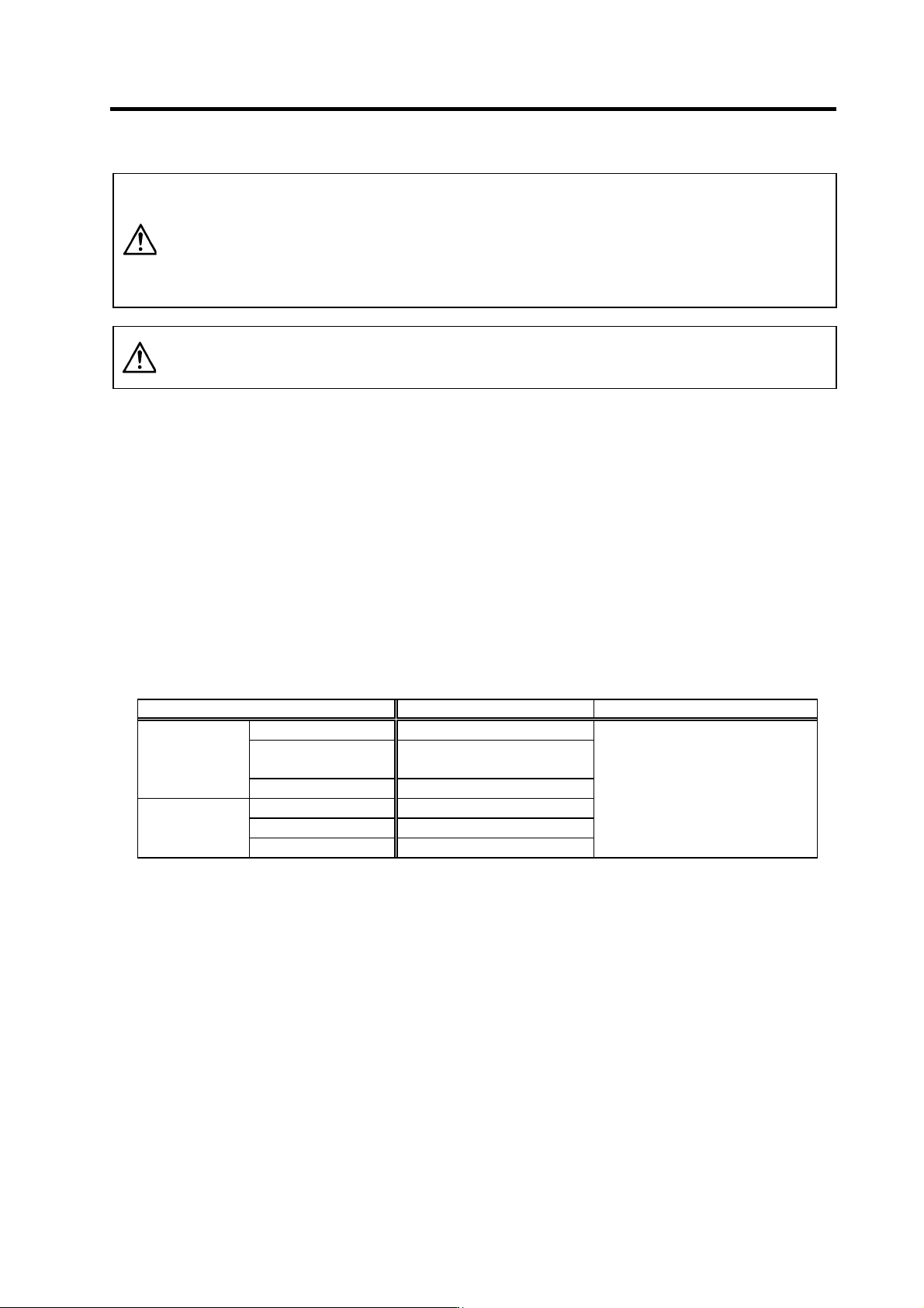
Part name Standard replacement time Remarks
Smoothing capacitor 10 years
Cooling fan
10,000 to 30,000 hours
(2 to 3 years)
Servo drive unit
Battery 10,000 hours
Bearings 20,000 to 30,000 hours
Detector 20,000 to 30,000 hours
Servomotor
Oil seal, V-ring 5,000 hours
The standard replacement time is a
reference. Even if the standard
replacement time is not reached, the
part must be replaced if any
abnormality is found.
[1] Power smoothing capacitor : The characteristics of the power smoothing capacitor will deteriorate
due to the effect of ripple currents, etc. The capacitor life is greatly
affected by the ambient temperature and working conditions.
However, when used continuously in a normal air-conditioned
environment, the service life will be ten years.
[2] Relays : Contact faults will occur due to contact wear caused by the
switching current. The service life will be reached after 100,000
cumulative switches (switching life) although thi s will differ according
to the power capacity.
[3] Servomotor bearings : The motor bearings should be re placed after 20,000 to 30,00 0 hours
of rated load operation at the rated speed. This will be affected by
the operation state, but the bearings must be replaced when any
abnormal noise or vibration is found in t he inspections.
[4] Servomotor oil seal, V-ring : These parts should be replaced after 5,000 hou rs of operatio n at the
rated speed. This will be affected by the operation state, but these
parts must be replaced if oil leaks, etc., a re fou nd in the inspections.