bnp-b2365(eng)b.pdf - 第355页
7. Maintenance 7 - 3 7-3 Adding and replacing units and parts CAUTION 1. Correctly transport the product accordin g to its weight. Failure to do so could result in injury . 2. Do not stack the product above the indicated…
7. Maintenance
7 - 2
WARNING
1. Before starting maintenance or inspections, turn the main circuit power and
control power both OFF. Wait at least ten minutes for the CHARGE lamp to
turn OFF, and then using a tester, confirm that the input and output voltage
are zero. Failure to observe this could lead to electric shocks.
2. Inspections must be carried out by a qualified technician. Failure to observ e
this could lead to electric shocks. Contact your nearest Mitsubishi branch or
dealer for repairs and part replacement.
CAUTION
1. Never perform a megger test (measure the insulation resistance) of the
servo drive unit. Failure to observe this could lead to faults.
2. The user must never disassemble or modify this product.
7-1 Inspections
Periodic inspection of the following items is recommended.
[1] Are any of the screws on the terminal block loose? If loose, tighten them.
[2] Is any abnormal noise heard from the servomotor bearings or brake section?
[3] Are any of the cables damaged or cracked? If the cables move with the machine, periodically
inspect the cables according to the working conditions.
[4] Is the core of the load coupling shaft deviated?
7-2 Service parts
A guide to the part replacement cycle is shown below. Note that these will differ according to the
working conditions or environmental conditions, so replace the parts if any abnormality is found.
Contact Mitsubishi branch or your dealer for repairs or part replacements.
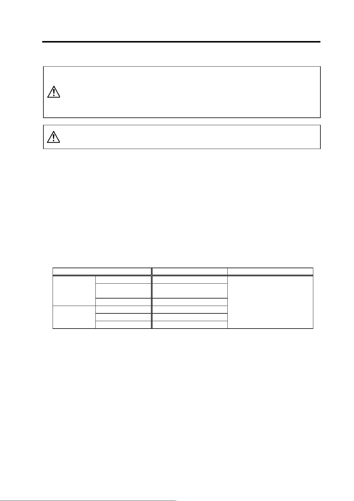
Part name Standard replacement time Remarks
Smoothing capacitor 10 years
Cooling fan
10,000 to 30,000 hours
(2 to 3 years)
Servo drive unit
Battery 10,000 hours
Bearings 20,000 to 30,000 hours
Detector 20,000 to 30,000 hours
Servomotor
Oil seal, V-ring 5,000 hours
The standard replacement time is a
reference. Even if the standard
replacement time is not reached, the
part must be replaced if any
abnormality is found.
[1] Power smoothing capacitor : The characteristics of the power smoothing capacitor will deteriorate
due to the effect of ripple currents, etc. The capacitor life is greatly
affected by the ambient temperature and working conditions.
However, when used continuously in a normal air-conditioned
environment, the service life will be ten years.
[2] Relays : Contact faults will occur due to contact wear caused by the
switching current. The service life will be reached after 100,000
cumulative switches (switching life) although thi s will differ according
to the power capacity.
[3] Servomotor bearings : The motor bearings should be re placed after 20,000 to 30,00 0 hours
of rated load operation at the rated speed. This will be affected by
the operation state, but the bearings must be replaced when any
abnormal noise or vibration is found in t he inspections.
[4] Servomotor oil seal, V-ring : These parts should be replaced after 5,000 hou rs of operatio n at the
rated speed. This will be affected by the operation state, but these
parts must be replaced if oil leaks, etc., a re fou nd in the inspections.
7. Maintenance
7 - 3
7-3 Adding and replacing units and parts
CAUTION
1. Correctly transport the product according to its weight. Failure to do so could
result in injury.
2. Do not stack the product above the indicated limit.
3. Installation directly on or near combustible materials could result in fires.
4. Install the unit as indicated at a place which can with stand the weight.
5. Do not get on or place heavy objects on the unit. Failure to observe this could
result in injury.
6. Always use the unit within the designated environment condition range.
7. Do not allow conductive foreign matter such as screws or metal chips, or
combustible foreign matter such as oil enter the servo drive or servomotor .
8. Do not block the intake or exhaust ports of the servo drive of servomotor.
Failure to observe this could result in fault s.
9. The servo drive and servomotor are precisi on devices. Do not drop them or
apply strong imp acts.
10. Do not install or operate a servo drive or servomotor which is damaged or
missing p a rts.
11. When the unit has been stored for a long time, contact the Service Center or
Service Station.
7-3-1 Replacing the drive unit
Replace the unit with the following procedures.
(1) Replacing the servo drive unit
[1] Disconnect the connectors connected to CN1A, CN1B, CN9, CN4, CN2L, CN3L, CN2M,
CN3M and CN20.
[2] Disconnect all wires connected to the terminal block: LU, LV, LW, MU, MV, MW, , L+, L-,
L11 and L21.
[3] Remove the two (four) screw fixing the unit onto the control unit. Remove the unit from the
control panel.
[4] Install the new unit following the removal procedures in reverse.
(Note) The connector and terminal block names differ for the MDS-C1-V1 unit. (CN2L, CN3L
→ CN2, CN3 LU, LV, LW → U, V, W)
The CN2M, CN3M connector and MU, MV, MW connectors are not provided.
(2) Replacing the spindle drive unit
[1] Disconnect the connectors connected to CN1A, CN1B, CN9, CN4, CN5, CN6, CN7 and CN8.
[2] Disconnect all wires connected to the terminal block: U, V, W, , L+, L-, L11 and L21.
[3] Remove the two (four) screw fixing the unit onto the control unit. Remove the unit from the
control panel.
[4] Install the new unit following the removal procedures in reverse.
(3) Replacing the power supply unit
[1] Disconnect the connectors connected to CN4, CN9 and CN23.
[2] Disconnect all wires connected to the terminal block's L1, L2, L3, , L+, L-, L11, L21 and
MC1.
[3] Remove the two (four) screw fixing the unit onto the control unit. Remove the unit from the
control panel.
[4] Install the new unit following the removal procedures in reverse.
7. Maintenance
7 - 4
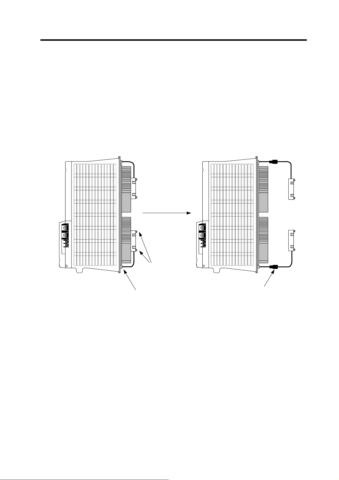
7-3-2 Replacing the unit fan
Replace the unit fan with the following procedures.
Replacement procedure
[1] Turn the NF for the 200/230VAC input power OFF, and wait for the CHARGE lamp on the
power supply unit to turn OFF before removing the unit.
[2] Remove the fan guard from the back of the power supply unit, and remove the two fan
mounting screws.
[3] Remove the rubber bushing for the fan power cable, and pull out the connection connector.
[4] Disconnect the connection connector, and replace the fan.
Remove the two screws
Remove the rubber bushing
Pull out the connection
connector and disconnect
the connector