bnp-b2365(eng)b.pdf - 第356页
7. Maintenance 7 - 4 7-3-2 Replacing the unit fan Replace the unit fan with the following procedure s. Replacement procedure [1] Turn the NF for the 200/230VAC input power OFF, and wait for the CHARGE lamp on the power s…
7. Maintenance
7 - 3
7-3 Adding and replacing units and parts
CAUTION
1. Correctly transport the product according to its weight. Failure to do so could
result in injury.
2. Do not stack the product above the indicated limit.
3. Installation directly on or near combustible materials could result in fires.
4. Install the unit as indicated at a place which can with stand the weight.
5. Do not get on or place heavy objects on the unit. Failure to observe this could
result in injury.
6. Always use the unit within the designated environment condition range.
7. Do not allow conductive foreign matter such as screws or metal chips, or
combustible foreign matter such as oil enter the servo drive or servomotor .
8. Do not block the intake or exhaust ports of the servo drive of servomotor.
Failure to observe this could result in fault s.
9. The servo drive and servomotor are precisi on devices. Do not drop them or
apply strong imp acts.
10. Do not install or operate a servo drive or servomotor which is damaged or
missing p a rts.
11. When the unit has been stored for a long time, contact the Service Center or
Service Station.
7-3-1 Replacing the drive unit
Replace the unit with the following procedures.
(1) Replacing the servo drive unit
[1] Disconnect the connectors connected to CN1A, CN1B, CN9, CN4, CN2L, CN3L, CN2M,
CN3M and CN20.
[2] Disconnect all wires connected to the terminal block: LU, LV, LW, MU, MV, MW, , L+, L-,
L11 and L21.
[3] Remove the two (four) screw fixing the unit onto the control unit. Remove the unit from the
control panel.
[4] Install the new unit following the removal procedures in reverse.
(Note) The connector and terminal block names differ for the MDS-C1-V1 unit. (CN2L, CN3L
→ CN2, CN3 LU, LV, LW → U, V, W)
The CN2M, CN3M connector and MU, MV, MW connectors are not provided.
(2) Replacing the spindle drive unit
[1] Disconnect the connectors connected to CN1A, CN1B, CN9, CN4, CN5, CN6, CN7 and CN8.
[2] Disconnect all wires connected to the terminal block: U, V, W, , L+, L-, L11 and L21.
[3] Remove the two (four) screw fixing the unit onto the control unit. Remove the unit from the
control panel.
[4] Install the new unit following the removal procedures in reverse.
(3) Replacing the power supply unit
[1] Disconnect the connectors connected to CN4, CN9 and CN23.
[2] Disconnect all wires connected to the terminal block's L1, L2, L3, , L+, L-, L11, L21 and
MC1.
[3] Remove the two (four) screw fixing the unit onto the control unit. Remove the unit from the
control panel.
[4] Install the new unit following the removal procedures in reverse.
7. Maintenance
7 - 4
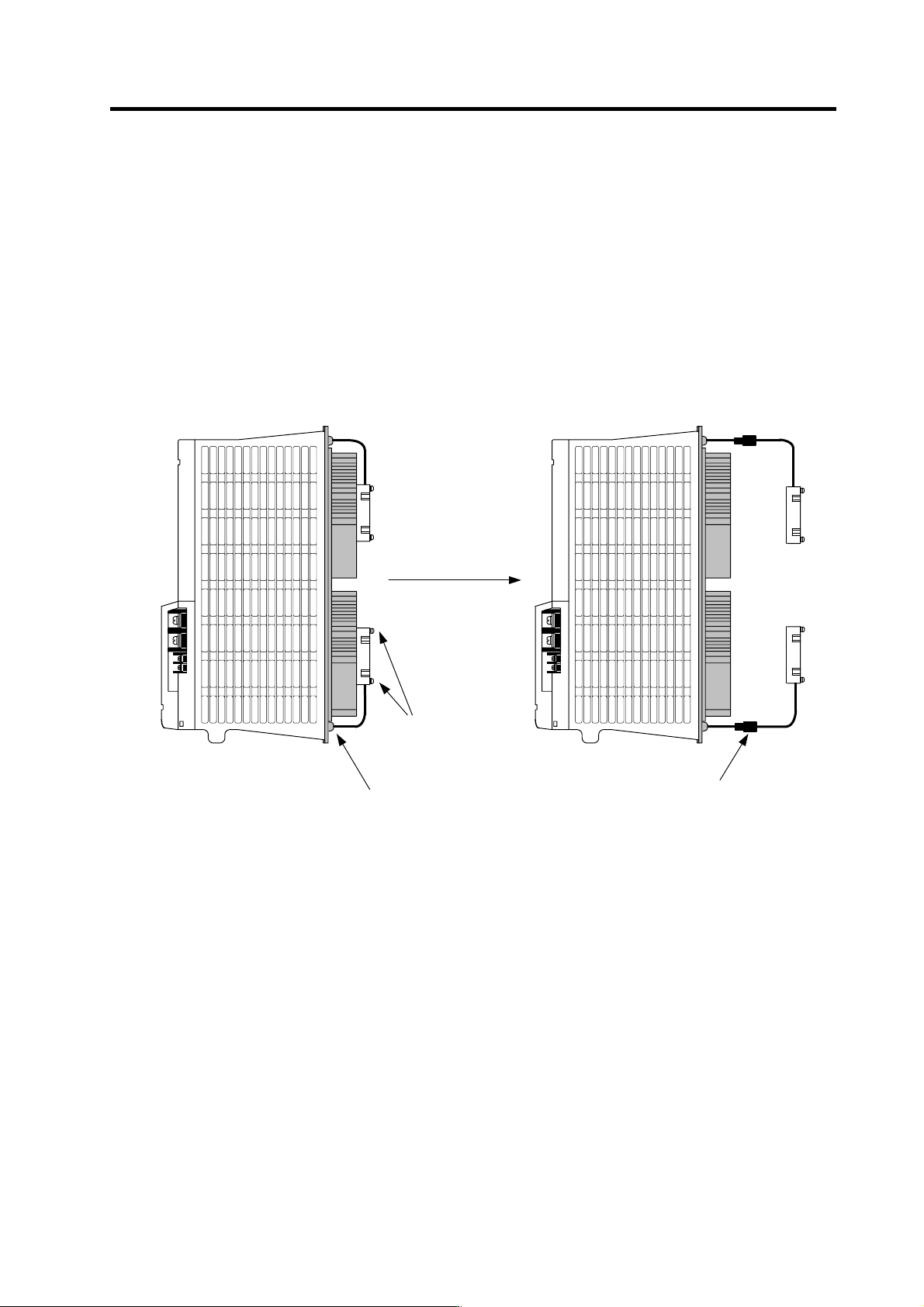
7-3-2 Replacing the unit fan
Replace the unit fan with the following procedures.
Replacement procedure
[1] Turn the NF for the 200/230VAC input power OFF, and wait for the CHARGE lamp on the
power supply unit to turn OFF before removing the unit.
[2] Remove the fan guard from the back of the power supply unit, and remove the two fan
mounting screws.
[3] Remove the rubber bushing for the fan power cable, and pull out the connection connector.
[4] Disconnect the connection connector, and replace the fan.
Remove the two screws
Remove the rubber bushing
Pull out the connection
connector and disconnect
the connector

Appendix 1. Cable and Connector Specifications
A1 - 1
Appendix 1-1 Selection of cable .........................................................................................................A1-2
Appendix 1-1-1 Cable wire and assembly ......................................................................................A1-2
Appendix 1-1-2 Flexible conduits ....................................................................................................A1-4
Appendix 1-2 Cable connection diagram............................................................................................A1-6
Appendix 1-3 Connector outline dimension drawings ......................................................................A1-12