bnp-b2365(eng)b.pdf - 第376页
Appendix 2. Compliance to EC Directives A2 - 4 (6) Selecting the w ire size for EC Directive compliance To comply with the EC Directives, select the wi re size from the following table using each drive unit's capaci…
Appendix 2. Compliance to EC Directives
A2 - 3
(3) Power supply
[1] If a control power supply of the drive unit is 200V, use the power supply under an Overvoltage
Protection Category II as stipulated in IEC60664. In that case, insert a star-connection
isolation transformer that is compliant with EN or IEC Standard into the primary input power
supply of the drive unit.
[2] Do not omit the circuit breaker and electromagnetic contactor.
(4) Earthing
[1] To prevent electric shocks, always connect the servo/spindle drive unit protective earth (PE)
terminal (terminal with
mark) to the protective earth (PE) on the control panel.
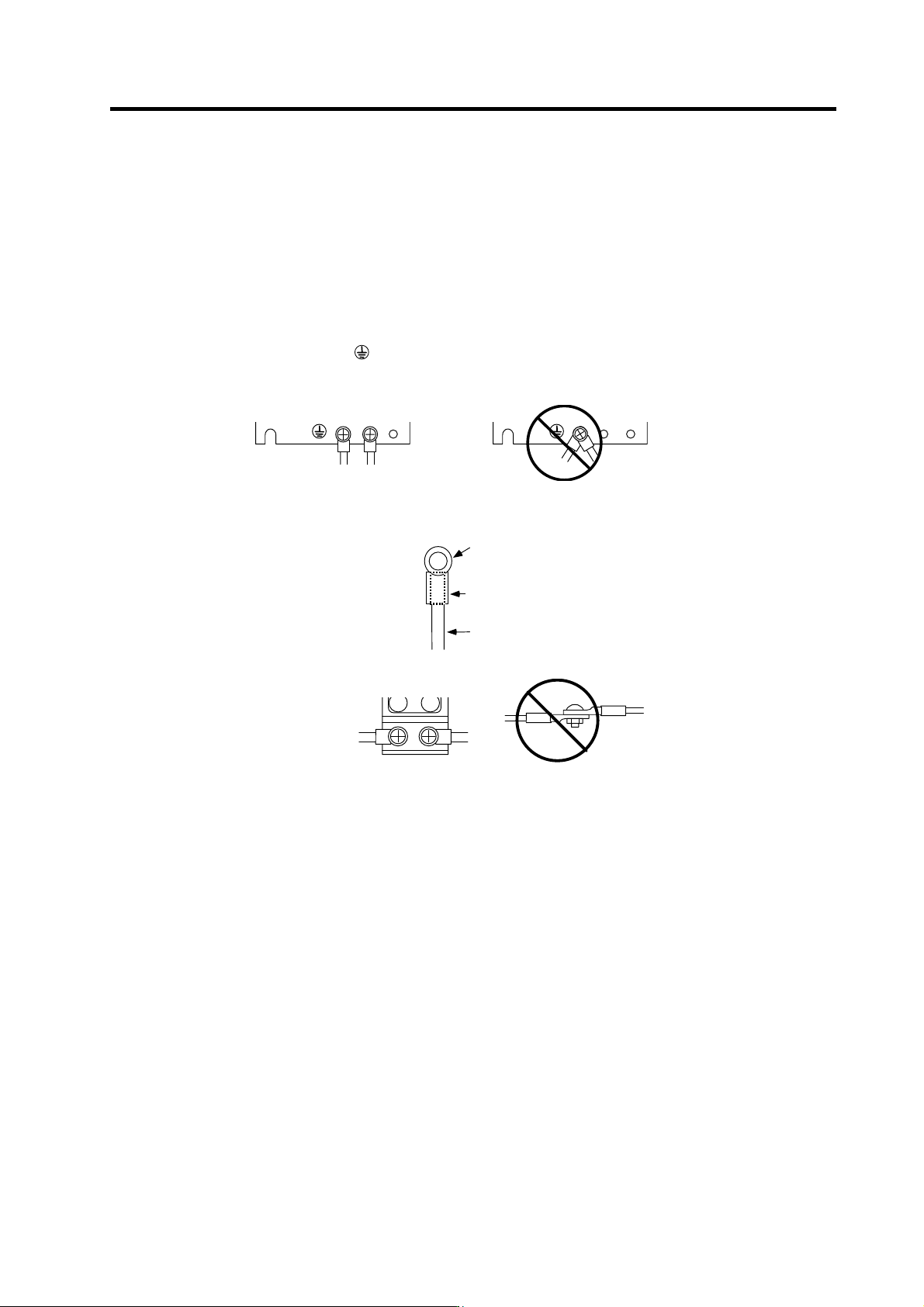
[2] When connecting the earthing wire to the protective earth (PE) terminal, do not tighten the
wire terminals together. Always connect one wire to one terminal.
PE terminal
PE terminal
(5) Wiring
[1] Always use crimp terminals with insulation tubes so that the connected wire does not contact
the neighboring terminals.
Crim p termi nal
Insul ation tube
Wire
[2] Do not connect the wires directly.
Appendix 2. Compliance to EC Directives
A2 - 4
(6) Selecting the wire size for EC Directive compliance
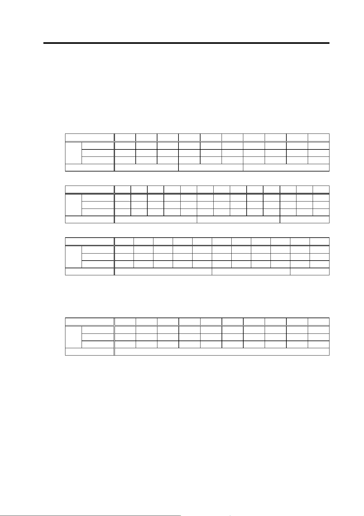
To comply with the EC Directives, select the wire size from the following table using each drive
unit's capacity as a reference.
The wire types are as follow.
PVC : Polyvinyl chloride
EPR : Ethylene polypropylene
SIR : Silicon rubber
[1] MDS-C1-CV (L1, L2, L3, PE) (The unit sizes are all mm
2
)
Type (MDS-C1-) CV-37 CV-55 CV-75 CV-110 CV-150 CV-185 CV-220 CV-260 CV-300 CV-370
PVC 2.5 2.5 4 6 10 16 25 35 50 70
EPR 1.5 2.5 4 6 10 16 25 35 35 50
Wire
SIR
1.0 1.5 2.5 4 6 10 16 16 25 25
Terminal screw size M4 M5 M8
[2] MDS-C1-SP (U, V, W, PE)
Type (MDS-C1-)
SP-04 SP-075 SP-15 SP-22 SP-37 SP-55 SP-75 SP-110 SP-150 SP-185 SP-220 SP-260 SP-300
PVC 1.0 1.0 1.0 1.0 1.5 2.5 4 6 10 16 25 35 70
EPR 1.0 1.0 1.0 1.0 1.5 2.5 4 6 10 16 25 35 50
Wire
SIR
1.0 1.0 1.0 1.0 1.0 1.0 2.5 4 6 10 10 16 25
Terminal screw size M4 M5 M8
[3] MDS-C1-V1/V2 (U, V, W, PE)
Type (MDS-C1-) V1-01 V1-03 V1-05 V1-10 V1-20 V1-35 V1-45 V1-70 V1-90 V1-110 V1-150
PVC 1.0 1.0 1.0 1.0 1.5 2.5 4 6 10 25 35
EPR 1.0 1.0 1.0 1.0 1.0 1.5 4 6 10 16 25
Wire
SIR
1.0 1.0 1.0 1.0 1.0 1.0 2.5 2.5 4 10 16
Terminal screw size M4 M5 M8
[4] Wire size for L11 and L21 link bar
Select a 1.5mm
2
wire or larger regardless of the capacity. (This also applies to the wire
between NFB-L11 and L21.)
[5] Wire size for L+ and L- link bar (For unified sizes)
Type (MDS-C1-) CV-37 CV-55 CV-75 CV-110 CV-150 CV-185 CV-220 CV-260 CV-300 CV-370
PVC 2.5 2.5 6 10 16 25 35 50 70 -
EPR 1.5 2.5 4 10 16 25 35 35 70 70
Wire
SIR
1.0 1.5 2.5 4 10 10 16 25 35 35
Terminal screw size M6
* The wire sizes in the above table comply with EN60204 under the following conditions.
• Ambient temperature 40°C
• Wire laid along wall or in open cable tray
When using under other conditions, refer to EN60204 Appendix 5 and Appended Material C.
Appendix 2. Compliance to EC Directives
A2 - 5
(7) Peripheral devices
[1] Use EN/IEC Standards compliant parts for the no-fuse breaker and contactor.
(8) Miscellaneous
[1] Refer to "MDS-C1 INSTRUCTION MANUAL" for methods on complying with the EMC
Directives.
[2] Ground the facility according to each country's requirements.
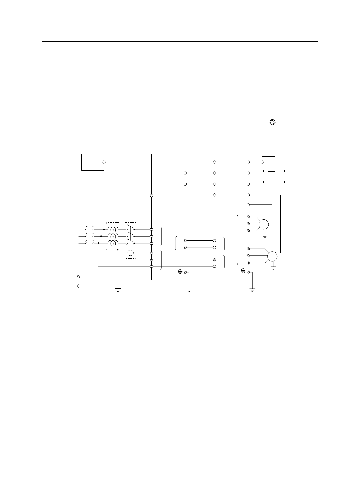
[3] The control circuit connector ({) is safely separated from the main circuit (
).
[4] Inspect the appearance before installing the unit. Carry out a performance inspection of the
final unit, and save the inspection records.
MC1
Mitsubishi CNC
SV1, 2
(CSH21)
External emergency
stop input
T
S
R
Contactor No-fuse
breaker
Ground
: Main circuit
: Control circuit
CN1A
CN23
CN4
CN9
CN20
L1
L2
L3
L11 TE3
TE1
CN9
CN1B
L+
L-
MU
MV
MW
CN2L
CN2M
LU
LV
LW
TE1
Motor end
detector
Motor end
detector
MDS-A-BT-
MDS-C1-V2-
MDS-C1-CV-
Motor
Motor
CN4
Machine end
detector
Machine end
detector
TE3
TE2
L+
L-
L11
L21
TE2
A
C reactor
Ground
Ground
L21
CN3M
CN3L
MC
External brake
output contact