bnp-b2365(eng)b.pdf - 第377页
Appendix 2. Compliance to EC Directives A2 - 5 (7) Peripheral devices [1] Use EN/IEC Standards compliant parts for the no-fuse breaker and contactor. (8) Miscellaneous [1] Refer to "MDS-C1 INSTRUCTION MANUAL" f…

Appendix 2. Compliance to EC Directives
A2 - 4
(6) Selecting the wire size for EC Directive compliance
To comply with the EC Directives, select the wire size from the following table using each drive
unit's capacity as a reference.
The wire types are as follow.
PVC : Polyvinyl chloride
EPR : Ethylene polypropylene
SIR : Silicon rubber
[1] MDS-C1-CV (L1, L2, L3, PE) (The unit sizes are all mm
2
)
Type (MDS-C1-) CV-37 CV-55 CV-75 CV-110 CV-150 CV-185 CV-220 CV-260 CV-300 CV-370
PVC 2.5 2.5 4 6 10 16 25 35 50 70
EPR 1.5 2.5 4 6 10 16 25 35 35 50
Wire
SIR
1.0 1.5 2.5 4 6 10 16 16 25 25
Terminal screw size M4 M5 M8
[2] MDS-C1-SP (U, V, W, PE)
Type (MDS-C1-)
SP-04 SP-075 SP-15 SP-22 SP-37 SP-55 SP-75 SP-110 SP-150 SP-185 SP-220 SP-260 SP-300
PVC 1.0 1.0 1.0 1.0 1.5 2.5 4 6 10 16 25 35 70
EPR 1.0 1.0 1.0 1.0 1.5 2.5 4 6 10 16 25 35 50
Wire
SIR
1.0 1.0 1.0 1.0 1.0 1.0 2.5 4 6 10 10 16 25
Terminal screw size M4 M5 M8
[3] MDS-C1-V1/V2 (U, V, W, PE)
Type (MDS-C1-) V1-01 V1-03 V1-05 V1-10 V1-20 V1-35 V1-45 V1-70 V1-90 V1-110 V1-150
PVC 1.0 1.0 1.0 1.0 1.5 2.5 4 6 10 25 35
EPR 1.0 1.0 1.0 1.0 1.0 1.5 4 6 10 16 25
Wire
SIR
1.0 1.0 1.0 1.0 1.0 1.0 2.5 2.5 4 10 16
Terminal screw size M4 M5 M8
[4] Wire size for L11 and L21 link bar
Select a 1.5mm
2
wire or larger regardless of the capacity. (This also applies to the wire
between NFB-L11 and L21.)
[5] Wire size for L+ and L- link bar (For unified sizes)
Type (MDS-C1-) CV-37 CV-55 CV-75 CV-110 CV-150 CV-185 CV-220 CV-260 CV-300 CV-370
PVC 2.5 2.5 6 10 16 25 35 50 70 -
EPR 1.5 2.5 4 10 16 25 35 35 70 70
Wire
SIR
1.0 1.5 2.5 4 10 10 16 25 35 35
Terminal screw size M6
* The wire sizes in the above table comply with EN60204 under the following conditions.
• Ambient temperature 40°C
• Wire laid along wall or in open cable tray
When using under other conditions, refer to EN60204 Appendix 5 and Appended Material C.
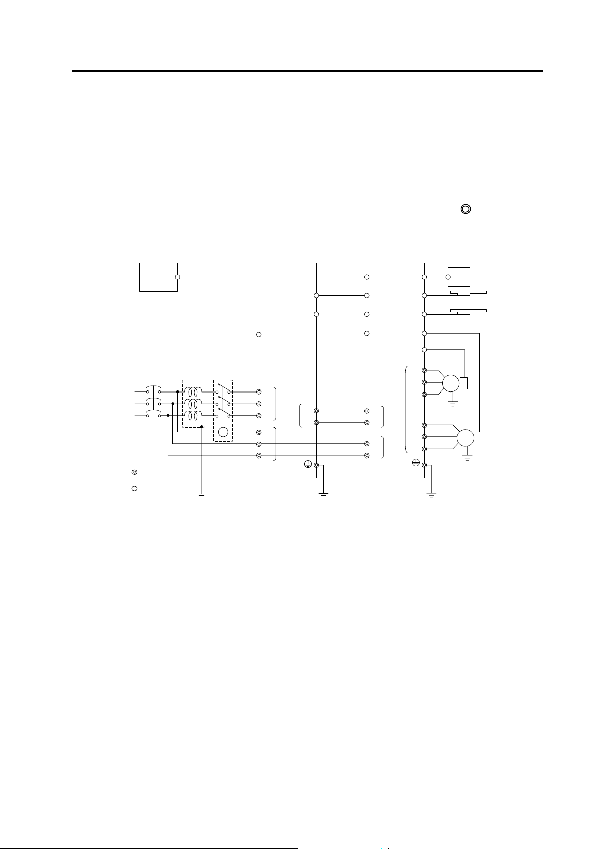
Appendix 2. Compliance to EC Directives
A2 - 5
(7) Peripheral devices
[1] Use EN/IEC Standards compliant parts for the no-fuse breaker and contactor.
(8) Miscellaneous
[1] Refer to "MDS-C1 INSTRUCTION MANUAL" for methods on complying with the EMC
Directives.
[2] Ground the facility according to each country's requirements.
[3] The control circuit connector ({) is safely separated from the main circuit (
).
[4] Inspect the appearance before installing the unit. Carry out a performance inspection of the
final unit, and save the inspection records.
MC1
Mitsubishi CNC
SV1, 2
(CSH21)
External emergency
stop input
T
S
R
Contactor No-fuse
breaker
Ground
: Main circuit
: Control circuit
CN1A
CN23
CN4
CN9
CN20
L1
L2
L3
L11 TE3
TE1
CN9
CN1B
L+
L-
MU
MV
MW
CN2L
CN2M
LU
LV
LW
TE1
Motor end
detector
Motor end
detector
MDS-A-BT-
MDS-C1-V2-
MDS-C1-CV-
Motor
Motor
CN4
Machine end
detector
Machine end
detector
TE3
TE2
L+
L-
L11
L21
TE2
A
C reactor
Ground
Ground
L21
CN3M
CN3L
MC
External brake
output contact

Appendix 3. EMC Installation Guidelines
A3 - 1
Appendix 3-1 Introduction ......................................................................................................................A3-2
Appendix 3-2 EMC instructions ..............................................................................................................A3-2
Appendix 3-3 EMC measures ................................................................................................................A3-3
Appendix 3-4 Measures for panel structure ...........................................................................................A3-3
Appendix 3-4-1 Measures for control panel unit.................................................................................A3-3
Appendix 3-4-2 Measures for door .....................................................................................................A3-4
Appendix 3-4-3 Measures for operation board panel .........................................................................A3-4
Appendix 3-4-4 Shielding of the power supply input section..............................................................A3-4
Appendix 3-5 Measures for various cables ............................................................................................A3-5
Appendix 3-5-1 Measures for wiring in panel .....................................................................................A3-5
Appendix 3-5-2 Measures for shield treatment...................................................................................A3-5
Appendix 3-5-3 Servo/spindle motor power cable..............................................................................A3-6
Appendix 3-5-4 Servo motor feedback cable .....................................................................................A3-7
Appendix 3-5-5 Spindle motor feedback cable...................................................................................A3-7
Appendix 3-6 EMC countermeasure parts .........................................................................................A3-8
Appendix 3-6-1 Shield clamp fitting.................................................................................................A3-8
Appendix 3-6-2 Ferrite core ............................................................................................................A3-9
Appendix 3-6-3 Power line filter ....................................................................................................A3-10
Appendix 3-6-4 Surge protector ....................................................................................................A3-15