bnp-b2365(eng)b.pdf - 第385页
Appendix 3. EMC Installation Guidelines A3 - 8 Appendix 3-6 EMC countermeasure parts Appendix 3-6-1 Shield clamp fitting The effect can be enhanced by connecting the c able directly to the earthing plate. Install an eart…
Appendix 3. EMC Installation Guidelines
A3 - 7
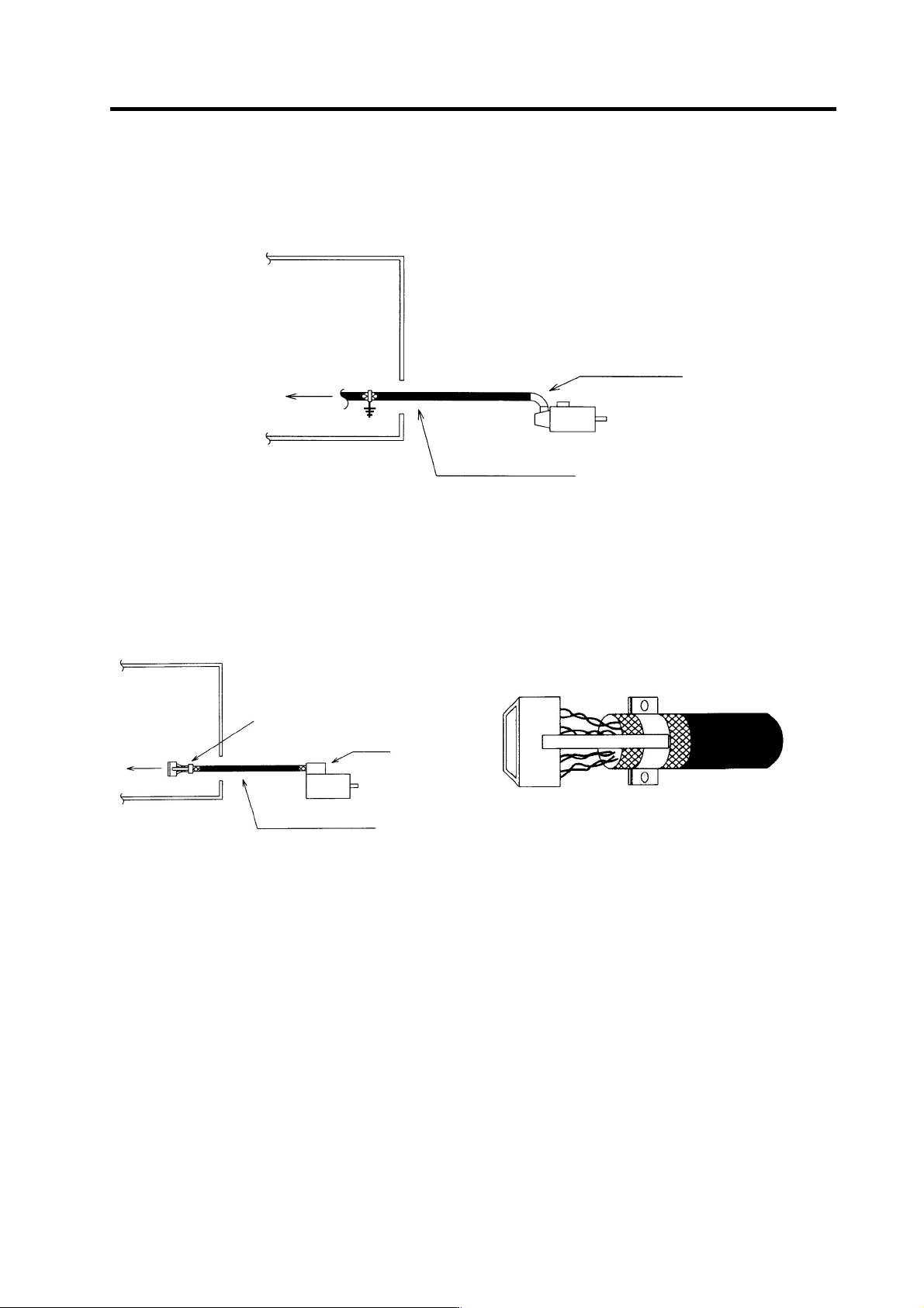
Appendix 3-5-4 Servo motor feedback cable
Use a conventional batch shield pair cable for feed back cable of the servo motor to earth on NC side
(inside the control panel.)
Control panel
To drive unit
Cannon connect or
Batch shield pair c able
Feed back cable for servomotor
Appendix 3-5-5 Spindle motor feedback cable
Use a conventional batch shield cable for feedback cable of the spindle motor.
To drive unit
Control pan el
Connect with connector case
after shield clamping
Terminal box
Batch pair shield cable
To drive unit
Spindle amp side connector (this figure shows when cover is removed)
(Note) Shield of the spindle motor feedback cable is not FG. Do not earth.
Feed back cable for spindle motor
Appendix 3. EMC Installation Guidelines
A3 - 8
Appendix 3-6 EMC countermeasure parts
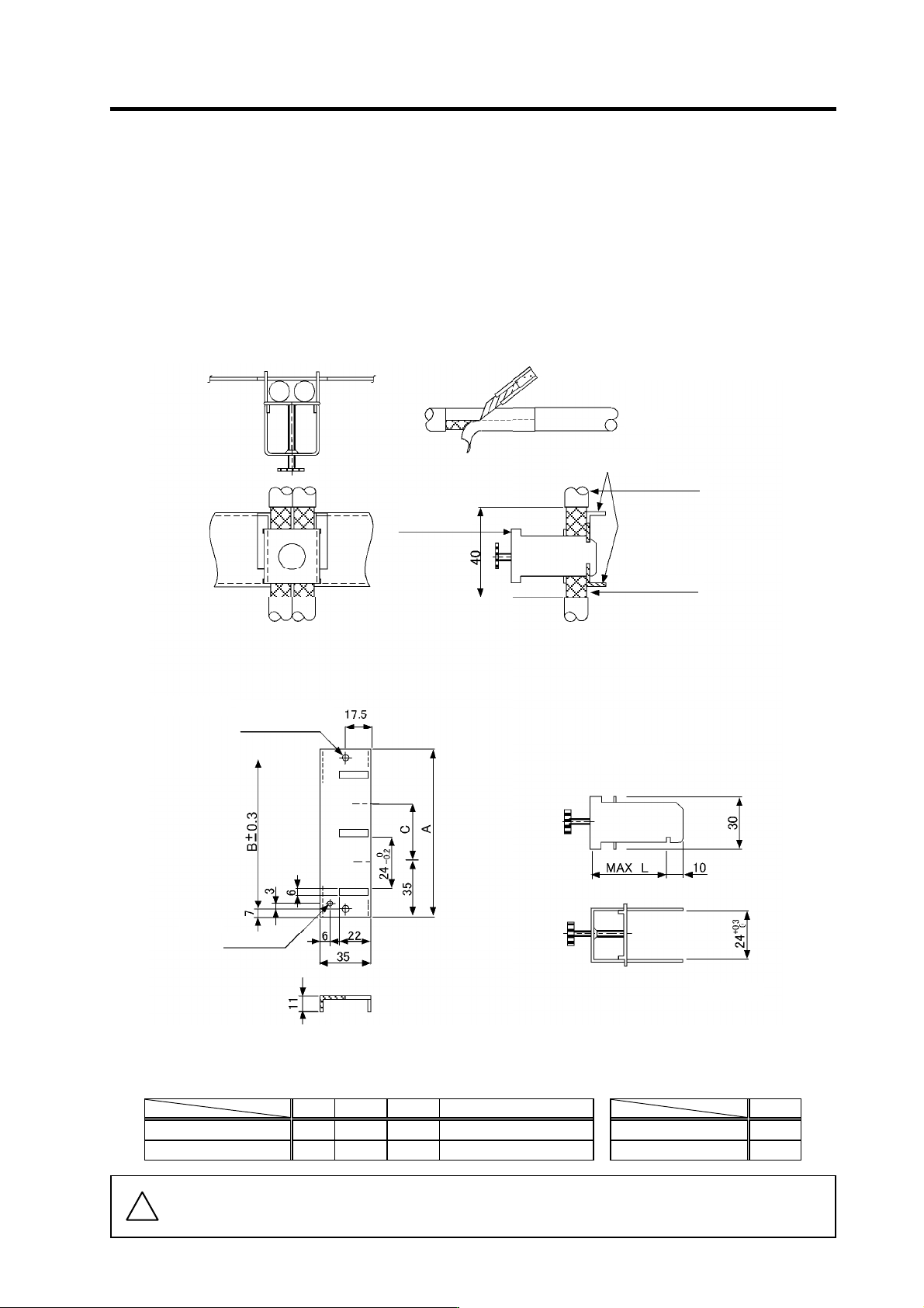
Appendix 3-6-1 Shield clamp fitting
The effect can be enhanced by connecting the cable directly to the earthing plate.
Install an earthing plate near each panel's outlet (within 10cm), and press the cable against the earthing
plate with the clamp fitting.
If the cables are thin, several can be bundled and clamped together.
Securely earth the earthing plate with the frame ground. Install directly on the cabinet or connect with an
earthing wire.
Contact Mitsubishi if the earthing plate and clamp fitting set (AERSBAN- SET) is required.
View of clamp section
• Outline drawing
Peel the cable sheath at the clamp section.
Cable
Cable
Earthing plate
Earthing plate
Clamp fitting
(Fitting A, B)
Clamp fitting
2-Ø5 hole
Installation hole
[Unit: mm]
Note 1
M4 screw
Shield sheath
(Note 1) Screw hole for wiring to earthing plate in cabinet.
(Note 2) The earthing plate thickness is 1.6mm.
A B C Enclosed fittings
L
AERSBAN-DSET 100 86 30 Clamp fitting A × 2 Clamp fitting A 70
AERSBAN-ESET 70 56 - Clamp fitting B × 1 Clamp fitting B 45
!
Caution
Shield of spindle detector cable is not connected to FG (earth). Do not earth the cable
shield with cable clamp, etc.
Appendix 3. EMC Installation Guidelines
A3 - 9
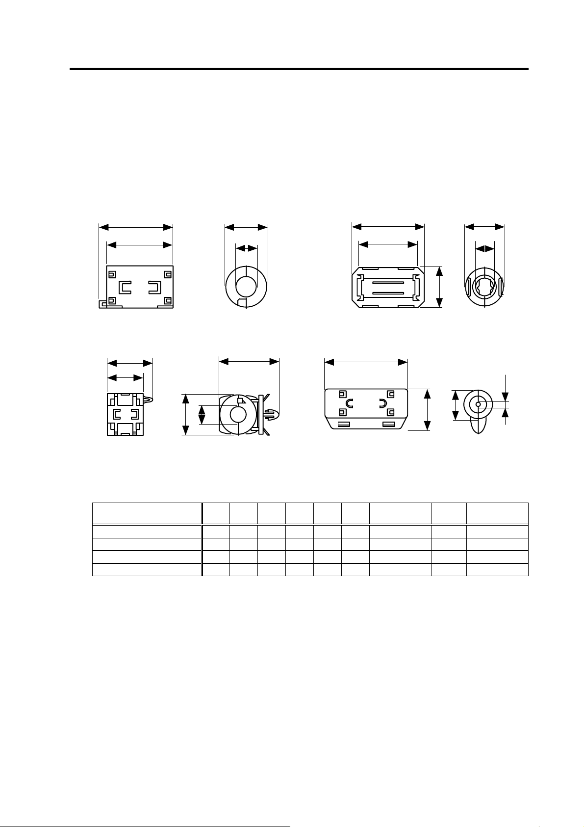
Appendix 3-6-2 Ferrite core
A ferrite core is integrated and mounted on the plastic case.
Quick installation is possible without cutting the interface cable or power cable.
This ferrite core is effective against common mode noise, allowing measures against noise to be taken
without affecting the signal quality.
A
B
φC
φD
A
B
D
E
φC
A
B
φ
C
φ
D
φ
C
φ
D
E
A
B
Recommended ferrite core
TDK ZCAT Series
Shape and dimensions
ZCAT type
ZCAT-B type ZCAT-C type
ZCAT-A type
Fig.2 Fig.1
Fig.3 Fig.4
[Unit: mm]
Part name Fig. A B C D E
Applicable
cable outline
Weight
Recommended
ferrite core
ZCAT3035-1330 (-BK)*
1
1 39 34 13 30 --- 13 max. 63 ○
ZCAT2035-0930-M (-BK) 2 35 29 13 23.5 22 10 to 13 29
ZCAT2017-0930-M (-BK) 3 21 17 9 20 28.5 9 max. 12
ZCAT2749-0430-M (-BK) 4 49 27 4.5 19.5 --- 4.5 max. 26
*1 A fixing band is enclosed when shipped.
ZCAT-B type: Cabinet fixed type, installation hole ø4.8 to 4.9mm, plate thickness 0.5 to 2mm
ZCAT-C type: Structured so that it cannot be opened easily by hand once closed.