bnp-b2365(eng)b.pdf - 第39页
1. Installation 1 - 23 [1] [2] [3] [4] [5] [6] [7] [8] Drive unit Sensor Servom otor S pindle motor M Receiver Instru- men t [2] [7] Sensor power supply Generated noise of drive sy stem Noise propagation path Measures [1…
1. Installation
1 - 22
1-5 Noise measures
Noise includes "propagation noise" generated from the power supply or relay, etc., and propagated
along a cable causing the power supply unit or drive unit to malfunction, and "radiated noise"
propagated through air from a peripheral device, etc., and causing the power supply unit or drive unit to
malfunction.
Always implement these noise measures to prevent the peripheral devices and unit from malfunctioning.
The measures differ according to the noise propagation path, so refer to the following explanation and
take appropriate measures.
(1) General noise measures
• Avoid laying the drive unit's power line and signal wire in a parallel or bundled state. Always
separate these wires. Use a twisted pair shielded wire for the detector cable and signal wires
such as the communication cable connected with the NC, and accurately ground the devices.
• Use one-point grounding for the drive unit and motor.
• Accurately ground the AC reactor.
(2) Propagation noise measures
Take the following measures when noise generating devices are installed and the power supply
unit or drive unit could malfunction.
• Install a surge killer on devices (magnetic contacts, relays, etc.) which generate high levels of
noise.
• Install a power line filter in the stage before the power supply unit.
• Install a ferrite core on the signal wire.
• Ground the shield of the servo detector's cable with a cable clamp.
• Wire the spindle PLG detector cable away from other wires.
(3) Measures against radiated noise
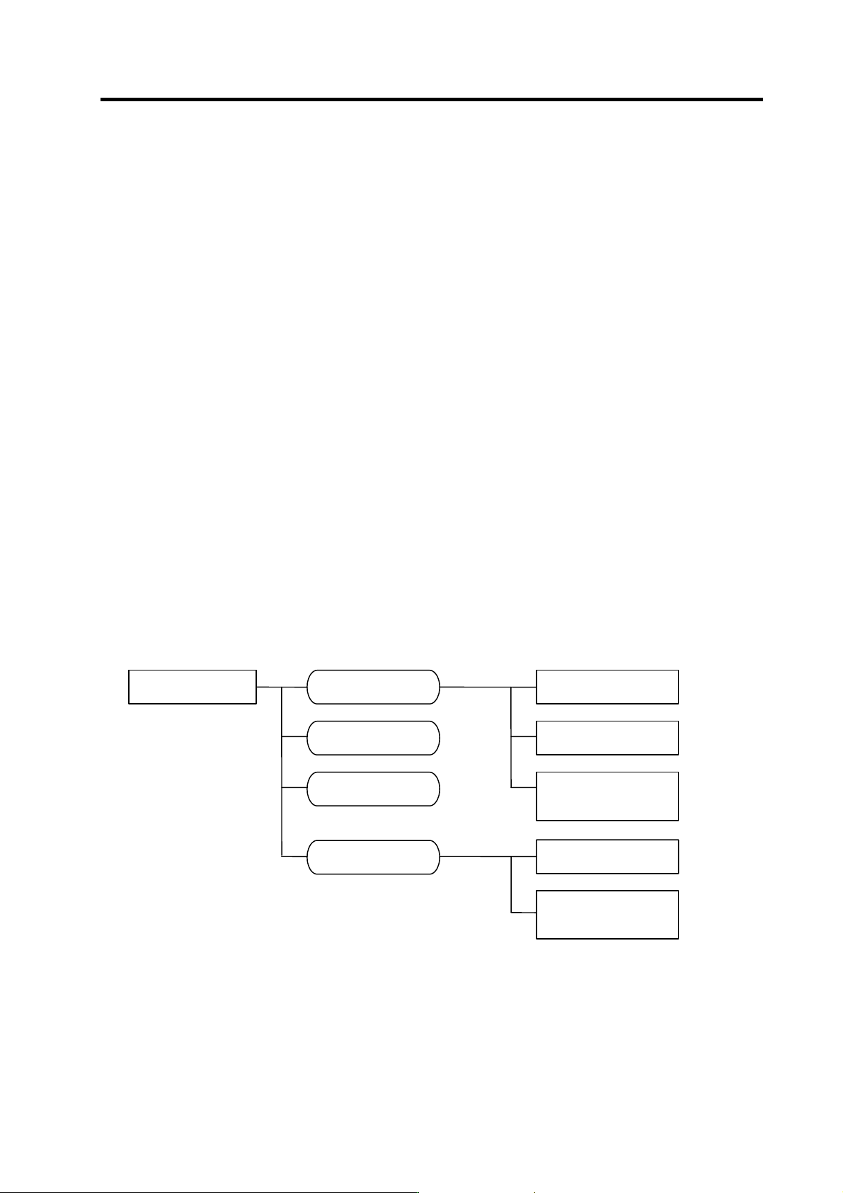
The types of propagation paths of the noise and the noise measures for each propagation path are
shown below.
Noise generated from
drive unit
Noise directly radiated
from drive unit
Airborne
propagation noise
Path [1]
Noise radiated from
power line
Magnetic induction
noise
Path [2]
Path [4]
and [5]
Noise radiated from
servomotor/spindle motor
Static induction
noise
Path [3]Path [6]
Noise propagated over
power line
Cable propagation
noise
Path [7]
Noise lead in from
grounding wire by
leakage current
Path [8]
1. Installation
1 - 23
[1]
[2]
[3]
[4]
[5]
[6]
[7]
[8]
Drive
unit
Sensor
Servomotor
S pindle motor
M
Receiver
Instru-
ment
[2]
[7]
Sensor
power
supply
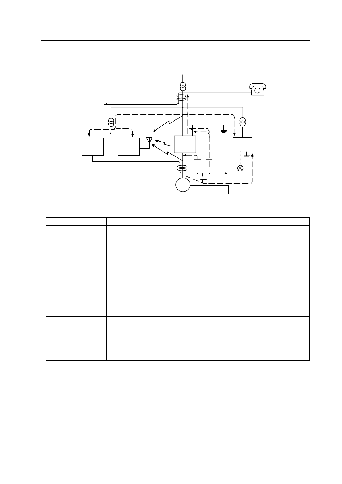
Generated noise of drive system
Noise propagation path Measures
[1] [2] [3]
When devices such as instrument, receiver or sensor, which handle minute signals and are easily
affected by noise, or the signal wire of these devices, are stored in the same panel as the drive
units and the wiring is close, the device could malfunction due to airborne propagation of the noise.
In this case, take the following measures.
(a) Install devices easily affected as far away from the drive units as possible.
(b) Lay devices easily affected as far away from the signal wire of the drive unit as possible.
(c) Avoid laying the signal wire and power line in a parallel or bundled state.
(d) Insert a line noise filter on the input/output wire or a radio filter on the input to suppress the
noise radiated from the wires.
(e) Use a shield wire for the signal wire and power line, or place in separate metal ducts.
[4] [5] [6]
If the signal w ire is laid in parallel to the pow er line, or if it is bundled with the pow er line, the noise
could be propagated to the signal wire and cause malfunction because of the magnetic induction
noise or static induction noise. In this case, take the following measures.
(a) Install devices easily affected as far away from the drive unit as possible.
(b) Lay devices easily affected as far away from the signal wire of the drive unit as possible.
(c) Avoid laying the signal wire and power line in a parallel or bundled state.
(d) Use a shield wire for the signal wire and power line, or place in separate metal ducts.
[7]
If the power supply for the peripheral devices is connected to the power supply in the same system
as the drive units, the noise generated from the power supply unit could back flow over the power
line and cause the devices to malfunction. In this case, take the following measures.
(a) Install a radio filter on the power supply unit's power line.
(b) Install a power filter on the power supply unit's power line.
[8]
If a closed loop is created by the peripheral device and drive unit's grounding wire, a leakage
current could flow and cause the device to malfunction.
In this case, change the device grounding methods and the grounding place.

2. Wiring and Connection
2 - 1
2-1 Part system connection diagram........................................................................................................ 2-3
2-2 Main circuit terminal block/control circuit connector .......................................................................... 2-4
2-2-1 Names and applications of main circuit terminal block signals and control circuit connectors... 2-4
2-2-2 Connector pin assignment .......................................................................................................... 2-5
2-3 NC and drive unit connection ............................................................................................................. 2-8
2-4 Motor and detector connection......................................................................................................... 2-11
2-4-1 Connecting the servomotor ....................................................................................................... 2-11
2-4-2 Connecting the full-closed loop system..................................................................................... 2-18
2-4-3 Connecting the synchronous control system ............................................................................ 2-22
2-4-4 Connection of the spindle motor ............................................................................................... 2-28
2-5 Connection of power supply............................................................................................................. 2-33
2-5-1 Power supply input connection .................................................................................................. 2-34
2-5-2 Connecting the grounding cable ............................................................................................... 2-37
2-5-3 Main circuit control ..................................................................................................................... 2-38
2-6 Wiring of the motor brake................................................................................................................. 2-39
2-6-1 Wiring of the motor magnetic brake .......................................................................................... 2-39
2-6-2 Dynamic brake unit wiring ......................................................................................................... 2-41
2-7 Peripheral control wiring.................................................................................................................... 2-42
2-7-1 Input/output circuit wiring............................................................................................................ 2-42
2-7-2 Spindle coil changeover ............................................................................................................ 2-43
2-7-3 Wiring of an external emergency stop....................................................................................... 2-46