bnp-b2365(eng)b.pdf - 第392页
Appendix 3. EMC Installation Guidelines A3 - 15 Appendix 3-6-4 Surge protector Insert a surge protector in the power input sect ion to prevent damage to the control panel or power supply unit, etc. caused by the surge (l…
Appendix 3. EMC Installation Guidelines
A3 - 14
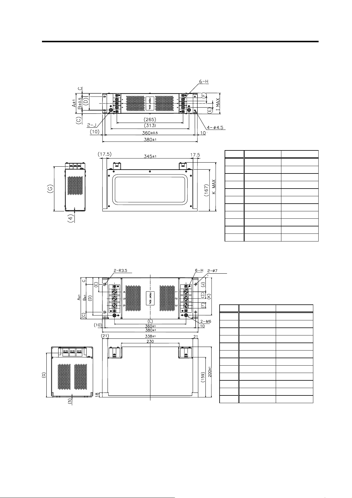
Outline dimension drawings
MX13030, MX13050
MX13100, MX13150
Model MX13030 MX13050
A 66 81
B 45 55
C 10.5 13
D 50 67
E 13 16
F 10 13
G 177 179
H M4 screw M6 screw
I 70 85
J M4 screw M6 screw
K 195 200
(Installation hole)
[Unit: mm]
Model MX13100 MX13150
A 130 165
B 90 110
C 20 27.5
D 115 150.5
E 37.5 57.5
F 18 23
G 174 176
H M6 screw M8 screw
I 21 27
J 37.5 56.5
K 115 149.5
L 276 284
(Installation hole)
(Installation hole)
[Unit: mm]
Appendix 3. EMC Installation Guidelines
A3 - 15
Appendix 3-6-4 Surge protector
Insert a surge protector in the power input section to prevent damage to the control panel or power
supply unit, etc. caused by the surge (lightning or sparks, etc.) applied on the AC power line.
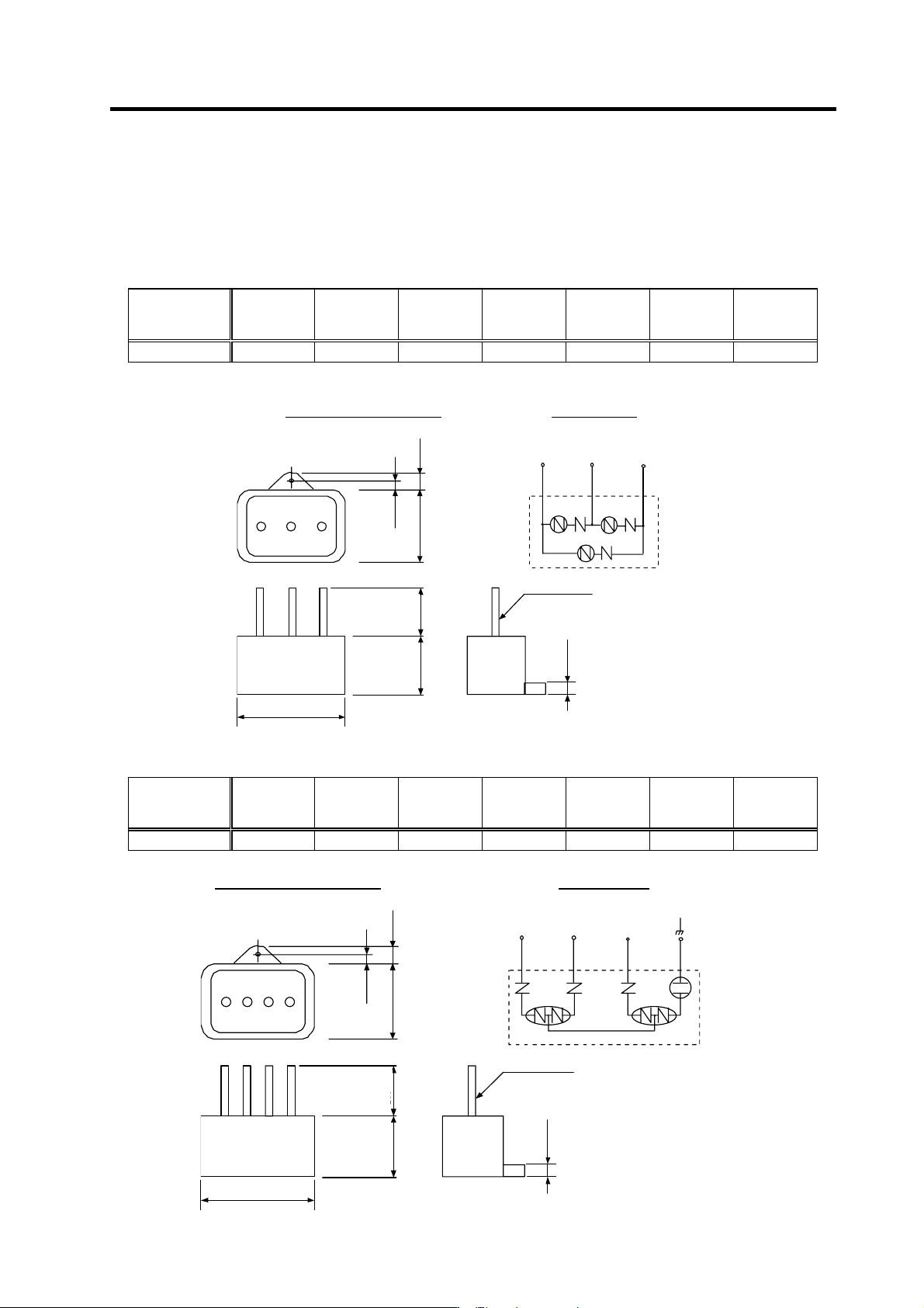
Use a surge protector that satisfies the following electrical specifications.
(1) 200V Surge protector
200V R・A・V BYZ Series
Part name
Circuit
voltage
50/60Hz
Maximum
tolerable
circuit voltag
e
Clamp
voltage
Surge
withstand
level
8/20 µS
Surge
withstand
voltage
1.2/50 µS
Electrostatic
capacity
Service
temperature
RAV-781BYZ-2 3AC 250V 300V 783V±10% 2500A 20kV 75pF -20 to 70°C
(Note) Refer to the manufacturer's catalog for details on the surge protector's characteristics and specifications.
2
8
.
5
±
1
5
.
5
±
1
1
1
±
1
2
8
±
1
2
0
0
±
3
0
0
41±1
4
.
5
±
0
.
5
Outline dimension drawings
Circuit diagram
[Unit: mm]
(1) Black
UL-1015 A WG16
(2) Black
(3) Black
41±1
28±1
200±
30
0
5.5±1
28.5±1
11±1
4.5±0.5
200V R・A・V BXZ Series
Part name
Circuit
voltage
50/60Hz
Maximum
tolerable
circuit voltag
e
Clamp
voltage
Surge
withstand
level
8/20 µS
Surge
withstand
voltage
1.2/50 µS
Electrostatic
capacity
Service
temperature
RAV-781BXZ-4 3AC 250V 300V 1700V±10% 2500A 2kV 75pF -20 to 70°C
(Note) Refer to the manufacturer's catalog for details on the surge protector's characteristics and specifications.
2
8
.
5
±
1
5
.
5
±
1
1
1
±
1
2
8
±
1
2
0
0
±
3
0
0
41±1
4
.
5
±
0
.
5
U
Outline dimension drawings
Circuit diagram
[Unit: mm]
(1) Black (2) Black (3) Black
UL-1015 A WG16
Green
41±1
28±1
200±
30
0
5.5±1
28.5±1
11±1
4.5±0.5
Appendix 3. EMC Installation Guidelines
A3 - 16
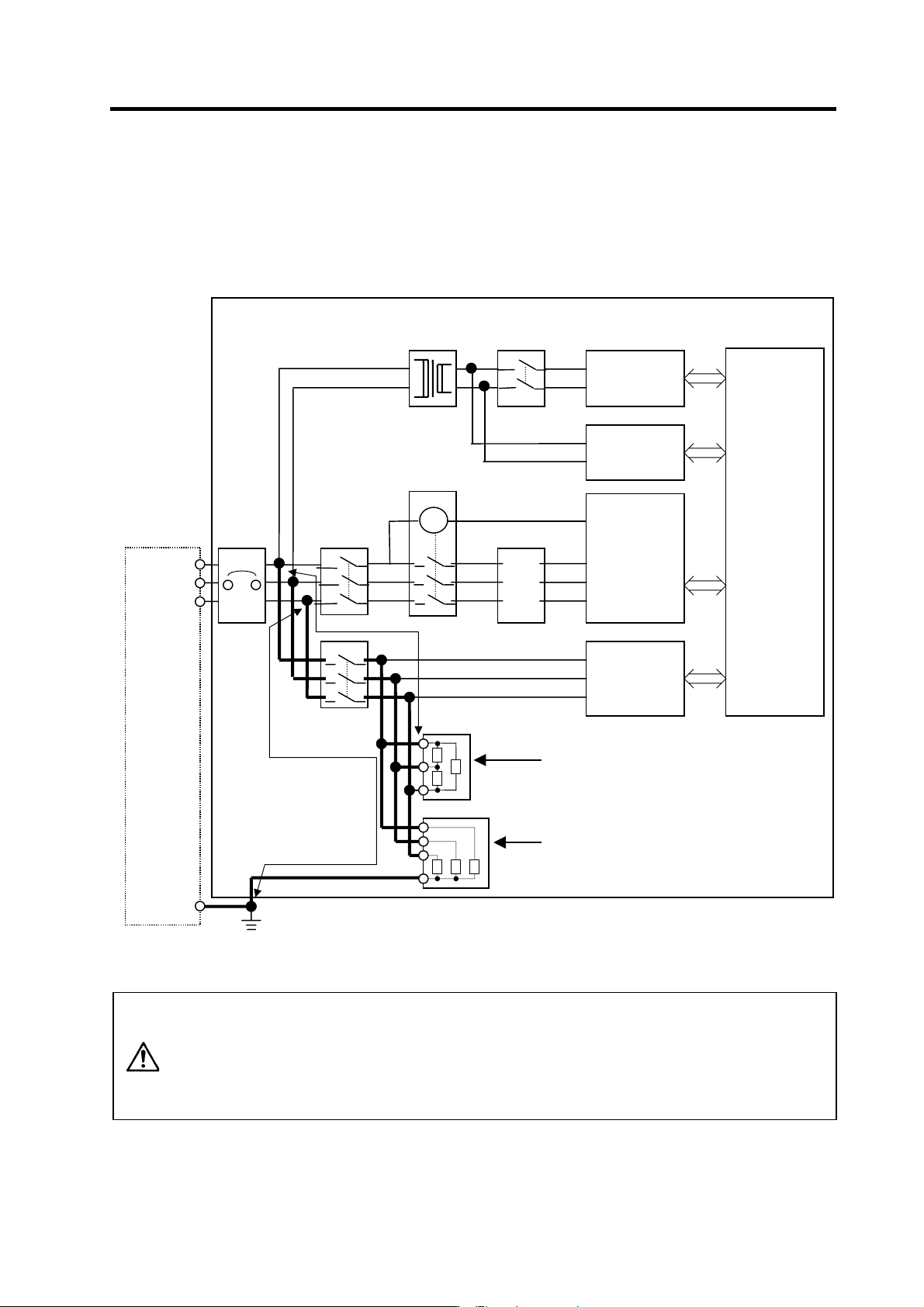
(2) Example of surge protector installation
An example of installing the surge protector in the machine control panel is shown below.
A short-circuit fault will occur in the surge protector if a surge exceeding the tolerance is applied.
Thus, install a circuit protection breaker in the stage before the surge protector. Note that almost no
current flows to the surge protector during normal use, so a breaker installed as the circuit
protection for another device can be used for the surge protector.
Installing the surge absorber
CAUTION
1. The wires from the surge protector should be connected without extensions.
2. If the surge protector cannot be installed just with the enclosed wires, keep
the wiring length of A and B to 2m or less. If the wires are long, the surge
protector's performance may drop and inhibit protection of the devices in the
panel.
3. Surge protector to be selected varies depending on input power voltage.
NC unit
Control panel
(relay panel,
etc.)
(1) Surge protector
(Protection across phases)
Other device
(panel power
su
pp
l
y,
etc.
)
Panel earth
leakage
breaker
Input
power
Breaker
AC reactor
Transformer
Grounding
Grounding plate
Factory
power
B
A
MC
Contactor
Breaker
Breaker
Power supply
unit
and
drive unit
Other device
(panel power
supply, etc.)
(2) Surge protector
(Protection across each phase's grounding)