bnp-b2365(eng)b.pdf - 第78页
2. Wiring and Connection 2 - 39 2-6 Wiring of the motor brake 2-6-1 Wiring of the motor magnetic brake The magnetic brake of servomotors with a magnetic brake is controlled by the motor brake control connector (CN20) on …
2. Wiring and Connection
2 - 38
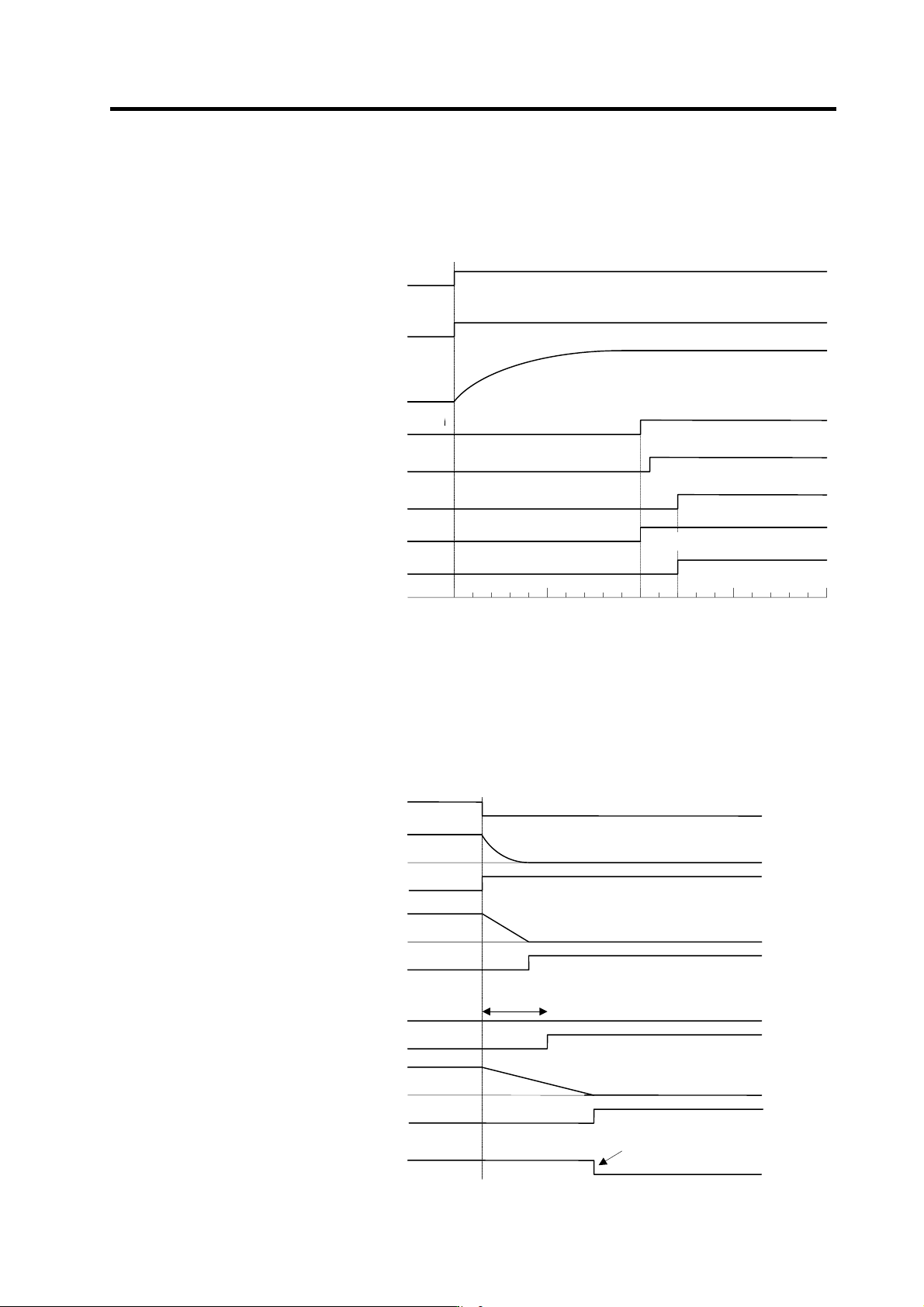
2-5-3 Main circuit control
(1) Contactor ON sequence
Main circuit power is turned ON in the sequence shown below when an emergency stop status is
canceled.
(2) Contactor shutoff sequence
When an emergency stop occurs, the NC checks the MC shutoff permission (motor stop or dynamic
brake operation) status for all axes and then shuts off the contactors. If there is no MC shutoff
permission output, the contactors are forced off 30 se conds later by their control units. Contactors
are shut off immediately if an alarm occurs.
OFF
ON
Emergency stop (EMG)
ON
OFF
Ready ON signal (READY)
ON
OFF
Servo ON signal (SERVO)
0
500 1000 1500
Time
(
ms
)
Command input enable
OFF
ON
Motor brake control output (CN20)
Dynamic brake
OFF
ON
Contactor control output (MC1)
ON
OFF
PN bus voltage
PN charging completed
Motor ON (GATE)
ON
OFF
Ready completion
Contactor ON sequence
Servo 1st axis
(Dynamic brake stop)
Servo 2nd axis
(Deceleration control)
Servo 3rd axis
(Drop prevention control)
0
0
0
MC shutoff
permission
Speed
MC shutoff
permission
Speed
MC shutoff
p
ermission
Speed
Contactor control output (MC1)
ON
OFF
Contactor shutoff sequence
Drop prevention
Shutoff after all-axes
permission check
OFF
ON
Emergency stop (EMG)
Spindle
(Deceleration stop)
0
MC shutoff
permission
Speed
2. Wiring and Connection
2 - 39
2-6 Wiring of the motor brake
2-6-1 Wiring of the motor magnetic brake
The magnetic brake of servomotors with a magnetic brake is controlled by the motor brake control
connector (CN20) on the servo drive unit. The servo drive unit releases the brake when the motor is ON.
(Servo ON means when torque is generated in the motor.)
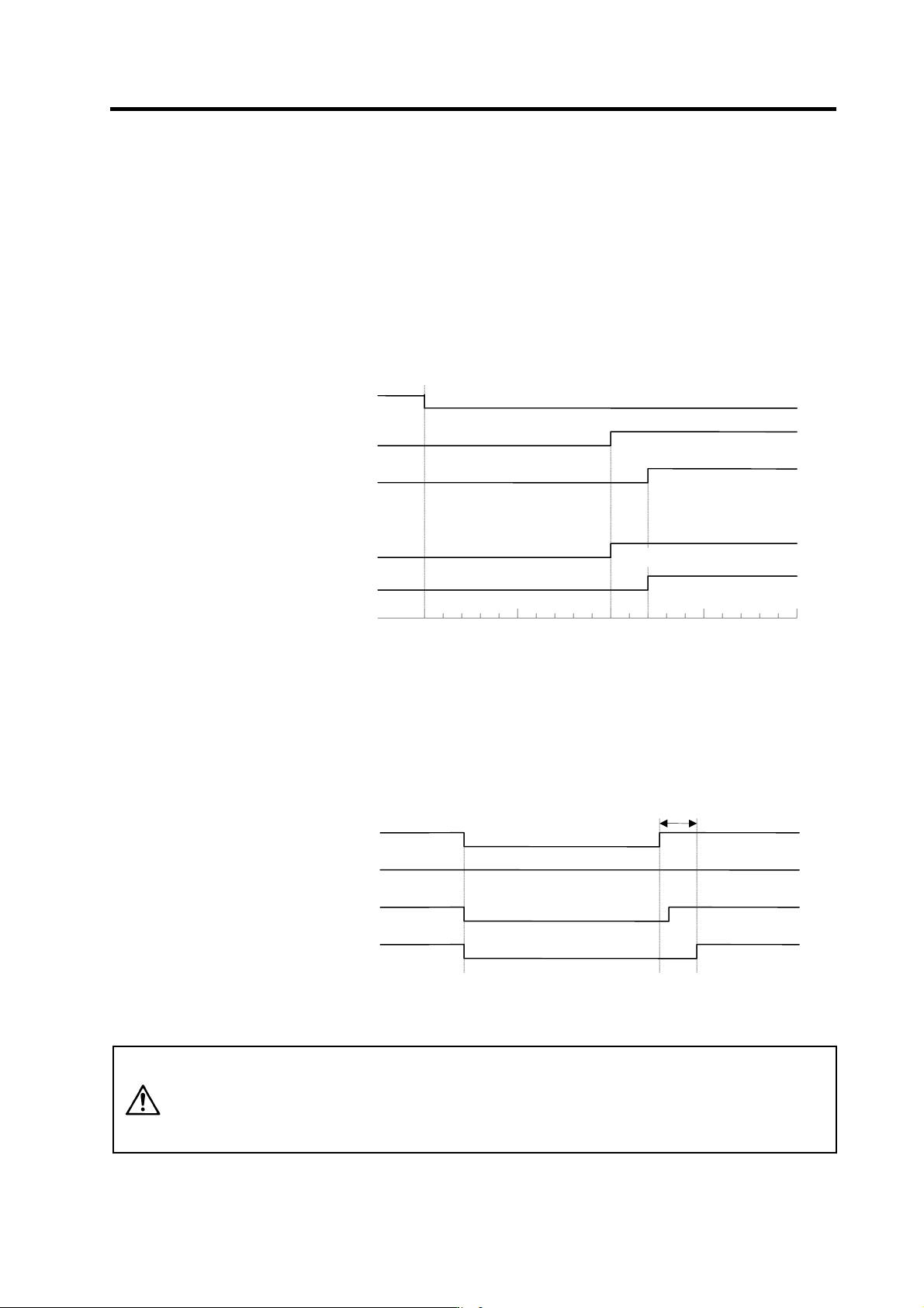
(1) Motor brake release sequence
The motor brake control output (CN20: MBR) releases the magnetic brake in the sequences in the
following drawing when canceling the emergency stop. The brake is released after the start of the
power ON to the servomotor.
ON
Cancel
Emergency stop (EMG)
ON
OFF
Servo ready signal (RDY)
ON
OFF
Servo ready completion
signal (SA)
0
500 1000 1500
Time (ms)
Command input enable
Cancel
ON
Motor brake control
output (MBR)
Dynamic brake
Cancel
ON
Ready completion
Motor brake control sequences when an emergency stop is canceled
(2) Control during the servo OFF command
When a servo OFF command is input by an NC sequence input, the motor brake turns ON
simultaneously when the motor ON is shut off. Note that the vertical axis drop prevention control is
not validated, so a drop due to the brake operation lag occurs. When the servo OFF is canceled, a
drop due to an uncontrolled state does not occur.
SERVO ON
SERVO OFF
Servo OFF command
OFF
ON
Motor brake control output
CN20 connector (MBR)
Dynamic brake
OFF
ON
Motor ON (GATE)
ON
OFF
Motor brake control sequences when a servo OFF command is output
200ms
CAUTION
1. The vertical axis drop prevention control only is performed during an
emergency stop (including alarms and power failures). It is not performed
when a servo OFF command is input.
2. A servo OFF command is required at both axes in order to perform a motor
brake control output (MBR) at 2-axis drive unit.
2. Wiring and Connection
2 - 40
(3) Operation sequences when an emergency stop occurs
The motor brake control output operation when an emergency stop occurs differs according to the
motor deceleration stop method. Refer to section "4-5 Setting for emergency stop" for details on the
operation sequences for each stop method.
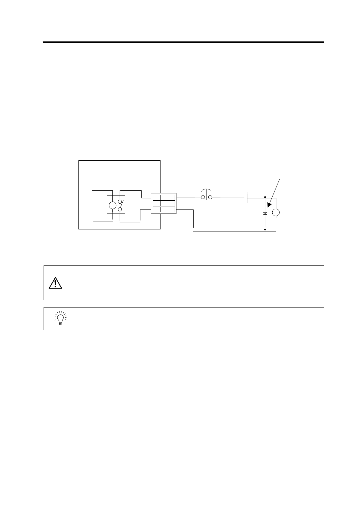
(4) Motor brake control connector (CN20) output circuit
As shown in the illustration below, an external power supply circuit is controlled by the CN20
connector output. Dynamic brake unit is controlled simultaneously for large-capacity drive unit
(MDS-C1-V1-110/150). Refer to "2-6-2 Dynamic brake unit wiring" for details.
(Unit internal relay specification: 5A 30Vdc/8A 250Vac)
CAUTION
1. Always install a surge absorber near the motor's brake terminal to eliminate
noise and protect the contacts.
2. The brakes cannot be released just by connecting the CN20 and motor brake
terminal. 24VDC must be supplied.
POINT
To ensure safety in an emergency, make sure that the magnetic brakes are
applied in sequence with the emergency stop switch.
A
lways install a surge
absorber
Brake
MDS-C1-V1/V2
3 MBR2
2
DBR
1 MBR1
CN20
24VDC
Surge
absorber
Emergenc
y
stop switch