bnp-b2365(eng)b.pdf - 第84页
2. Wiring and Connection 2 - 45 (3) Wiring The illustration below shows the 2 types of c hangeover that occur after a coil changeover, (a) Y (star) – ∆ (delta) changeover, and (b) Y (star) – Y (sta r) changeover. As show…
2. Wiring and Connection
2 - 44
(2) Protective functions
[1] Base shutoff after a winding changeover
When the L-coil selection command (LCS) is used to perform low-speed winding → high-speed
winding switching, or vice-versa, the base is shut off during contactor operation time in order to
protect the spindle drive unit's main circuit. The base shutoff time is determined by the "Winding
changeover base shutoff timer" (SP059) setting. The standard time setting should be used, as a
shorter time can cause contactor burn damage.
(Refer to 5-2-2 (4) "Spindle control output 4" Coil changing (bit 6) for details.)
No. Abbrev. Parameter name Description Setting range
Standard
value
SP059 MKT* Winding
changeover base
shut-off timer
Set the base shut-off time for contactor switching at coil
changeover.
Note that the contactor may be damaged with burning if the
value of this parameter is too small.
50 to 10000
(ms)
150
[2] Current limit after coil changeover
Following a coil changeover, the current is limited (SP061) for the period specified by the current
limit timer (SV060) in order to stabilize control. Because position loop control (synchronous tap,
C-axis control, etc.) that occurs immediately after a coil changeover will result in unstable control,
be sure that position commands specified by the sequence is input after the current limit is
cancelled.
No. Abbrev. Parameter name Description Setting range
Standard
value
SP060 MKT2* Current limit timer
after coil
changeover
Set the current limit time to be taken after completion of
contactor switching at coil changeover.
0 to 10000
(ms)
500
SP061 MKIL* Current limit value
after coil
changeover
Set the current limit value during a period defined in SP060
(MKT2) after completion of contactor switching at coil
changeover.
0 to 120 (%) 75
2. Wiring and Connection
2 - 45
(3) Wiring
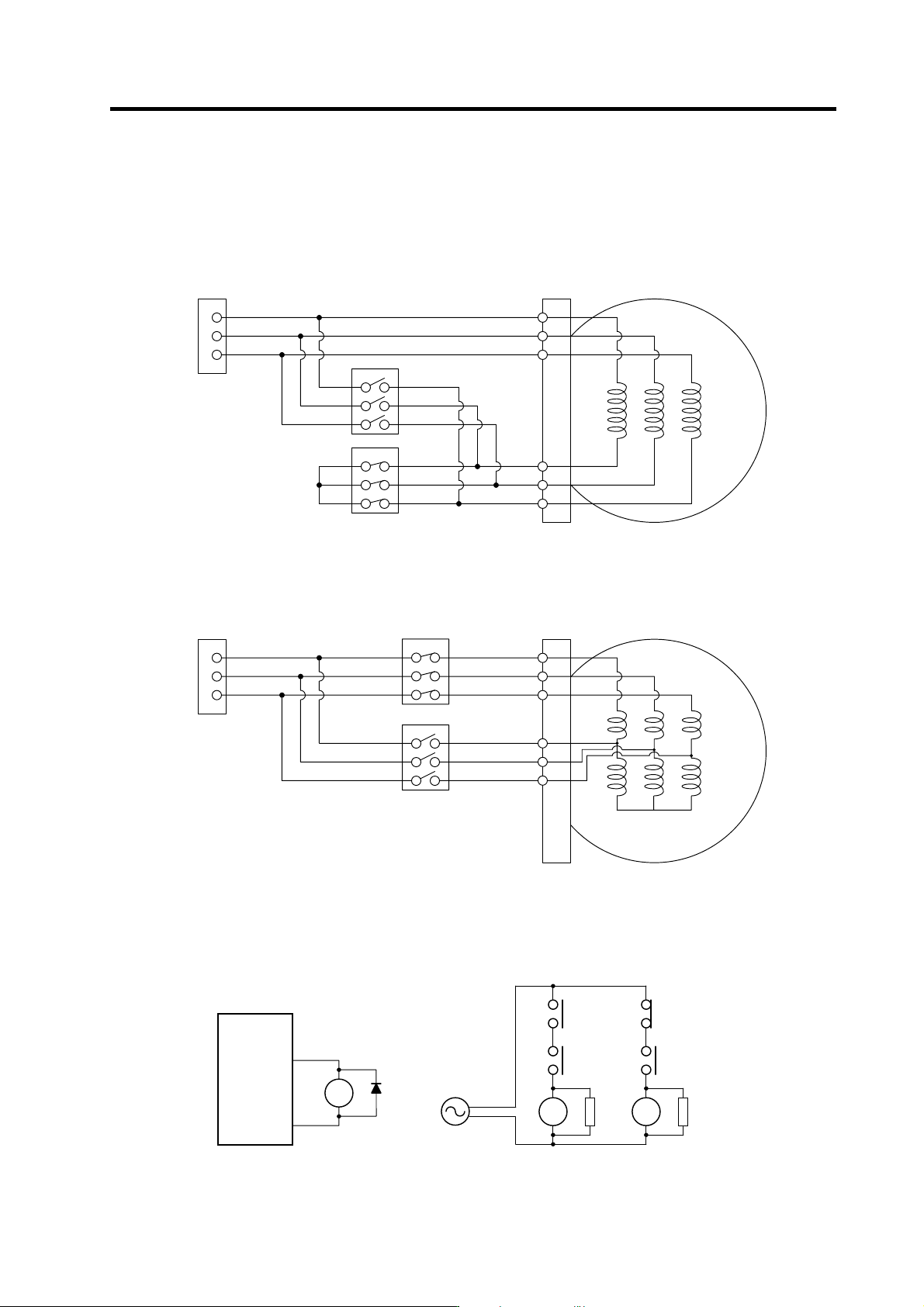
The illustration below shows the 2 types of changeover that occur after a coil changeover, (a) Y
(star) – ∆ (delta) changeover, and (b) Y (star) – Y (star) changeover. As shown in (c), one of the
contactors (MC1 or MC2) is turned ON and the other is turned OFF at all of the coil changeover
control circuits.
U
V
W
X
Y
Z
U
V
W
MC2
MC1
S
p
indle moto
r
Spindle drive unit
terminal block
MC1: Contactor to connect low-speed coil (Y-connection)
MC2: Contactor to connect high-speed coil (∆-connection)
(a) Y (star) - ∆ (delta) changeover circuit
U1
V1
W1
U2
V2
W2
U
V
W
MC1
Spindle motor
Spindle drive unit
terminal block
MC2
MC1: Contactor to connect low-speed coil (1st Y-connection)
MC2: Contactor to connect high-speed coil (2nd Y-connection)
(b) Y (star) - Y (star) changeover circuit
(c) Coil changeover control circuit (common)
Coil changeover relay control circuit
CN9-8
CN9-10
MDS-C1-SP
RA
MC1 SK
MC2
RA
S
T
MC2 SK
MC1
RA
2. Wiring and Connection
2 - 46
2-7-3 Wiring of an external emergency stop
(1) External emergency stop setting
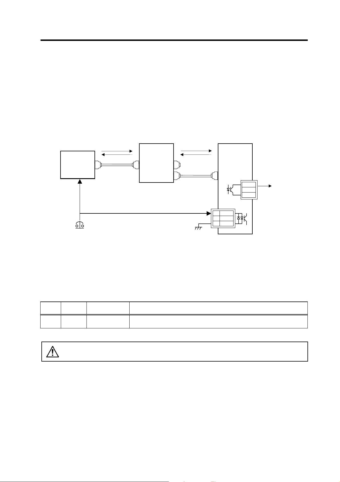
Besides the emergency stop input from the NC communication cable (CN1A, CN1B),
double-protection when an emergency stop occurs can be provided by directly inputting an external
emergency stop to the CN23 connector on the power supply unit. Even if the emergency stop is not
input from CNC for some reason, the contactors will be shut off by the external emergency stop
input from CN23 connector on the power supply unit.
[1] Connection
[2] Setting
When using the external emergency stop, the rotary switch on the front of the power supply unit and
the parameter (PTYP) of drive unit that controls the power supply must be set.
• Rotary switch setting: 4
• Parameter setting: Add "0040" to the setting of PTYP (Servo=SV036, Spindle=SP041).
Parameter settings
No.
Abbrevia-
tion
Parameter name Descriptions
SV036
SP041
PTYP Power supply type
When external emergency stop is validated, 0040 [hex] is added to PTYP for the drive
unit connected to the power supply unit.
CAUTION
The emergency stop signal input to the CNC side cannot be used as a substitute
for the external emergency stop function (CN23).
Mitsubishi NC
External emergency stop input
MDS-C1-V1/V2/SP
CN1A
CN4
MDS-C1-CV
CN4
CN1B
1 EMG1
2
N
C
3 EMG2
MC1
Emergency
stop
Alarm
Alarm
Contactor shutoff
command
CN23
MC1
L
21
L
11
SV1,2
SH21
FCUA-R000
FCUA-R000
SH21
Emergency
stop