Plan_HF3_14_20_en line 1电路.pdf - 第17页
Pag e = C1 HF =HF +C1/40 35 Modificati on Date Na m e No rm Check. Proj. Origin Date Crea. f. schb ERSA DIC 18 .0 6. 200 9 18. 07 .2 006 =HF +C1/30 133 953- V00 Ot to-Schott-Straße 5 97 87 7 W ertheim Gm bH Pr oj e c t n…
Page
=
C1
HF
=HF+C1/35
30
Modification Date
Name Norm
Check.
Proj.
Origin
Date
Crea. f.
schb
ERSA
DIC
18.06.2009
=HF+C1/25
133953-V00
Otto-Schott-Straße 5
97877 Wertheim
GmbH
Project name
14:15:0508.07.2010
+
file name (*.pdf)
133953-V00_100705
basic-project
-
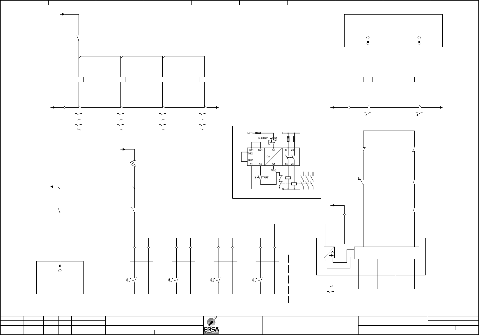
emergency off
Hotflow 3/xx
PDF-Page
Plant designation
BU
0,50
0,50
BU
BU
0,50
0,50
BU
0,50
BU
0,50
BU
BU
0,50
0,50
BU
BU
0,50
BU
0,50
BU
0,50
BU
0,50
BU
0,50
BU
0,50
BU
0,50
0,50
BU
BU
0,50
BU
0,50
BU
0,50
BU
0,50
BU
0,50
0,50
BU
0,50
BU
0,50
BU
0,50
BU
0,50
BU
-22K1
.07
24VDC
power on
12
11
14
/10.06 / -24V-G(1)
/10.09 / -GND-X5
1
-22X5.1
2 34
-22S1
emergency off switch
front on the left
1.1
1.2
-22S2
emergency off switch
front on right
1.1
1.2
-22WS2
H05VV5-F
0,75
2
1 2
-22S3
emergency stop
bottom
in the back left
1.1
1.2
-22WS3
H05VV5-F
0,75
2
1 2
5 6
-22S4
emergency stop
bottom
in the back right
1.1
1.2
-22WS4
H05VV5-F
0,75
2
1 2
78
-22F1
2,0AT
supply
emergency stop
2
1
.01 / -22A1:A1
.01 / -22A1:A1
/10.09 / -GND-X5
24VDC
emergency stop contactor 1
400VAC/16A
-22K3
1 2
/5.06
3 4
/5.06
5 6
/5.06
22 21
.07
A1
A2
24VDC
emergency stop contactor 2
400VAC/16A
-22K4
2 1
/5.06
4 3
/5.06
6 5
/5.06
21 22
.08
A1
A2
-22K3
.01
24VDC
emergency stop contactor 1
400VAC/16A
22
21
-22K4
.02
24VDC
emergency stop contactor 2
400VAC/16A
21
22
24VDC
emergency stop
connecter 1 hood
24VDC/16A
-22K5
1 2
/40.03
3 4
/45.01
5 6
/355.01
22 21
.08
A1
A2
24VDC
emergency stop
connecter 2 hood
24VDC/16A
-22K6
2 1
/40.03
4 3
/45.01
6 5
/355.01
21 22
.08
A1
A2
-22K6
.04
24VDC
emergency stop
connecter 2 hood
24VDC/16A
21
22
-22K5
.03
24VDC
emergency stop
connecter 1 hood
24VDC/16A
22
21
-22WS1
H05VV5-F
0,75
2
1 2
/10.09 / -GND-X5
24VDC
power on
-22K1
12
1114
.07
A1
A2
-GND-K / /65.06
/115.00
/380.00
/415.08
/500.01
/390.07
/440.04
/440.07
/445.07
/445.04
/450.04
/450.07
/455.04
/455.07
/480.05
/490.05
/210.07
/120.00
/385.00
/460.04
/460.07
/465.04
/465.07
/110.00
/395.00
/470.04
/470.07
/475.04
/475.07
/175.06
/370.06
/40.07
/520.08
-16
-X5
-18
-X5
-20
-X5
-A1
X20DM9324
8xDI / 4xDO
/10.04
-A1
X20DM9324
8xDI / 4xDO
/10.04
power on
IF6.ST1.DO.02
25
IF6.ST1.DI.03
emergency stop activ
12
24VDC
power off
-22K2
12
1114
.02
A1
A2
power off
IF6.ST1.DO.03
16
-22K2
.08
24VDC
power off
12
11
14
-22K6:A2 /
=HF
+E1
emergency
off device
-22A1
13 14
.01
23 24
.01
supply
control logic
A1 A2 X1 X2
S11 S21 S12 S22
-22A1
.06
emergency
off device
13
14
-22A1
.06
emergency
off device
23
24
-22A1
0 1 2 3 4 5 6 7 8 9
Page
=
C1
HF
=HF+C1/40
35
Modification Date
Name Norm
Check.
Proj.
Origin
Date
Crea. f.
schb
ERSA
DIC
18.06.200918.07.2006
=HF+C1/30
133953-V00
Otto-Schott-Straße 5
97877 Wertheim
GmbH
Project name
14:15:0508.07.2010
+
file name (*.pdf)
133953-V00_100705
basic-project
-
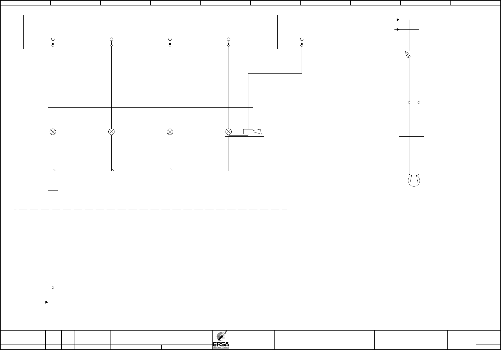
signal light
fan switch cabinet
Hotflow 3/xx
PDF-Page
Plant designation
0,50
BU
/10.09 / -GND-X5
-23H1
green
signal lamp green
1
0
-23WH1
Kaufteil
0,34
6
BN
WH
BU
GY
PK
-23WH1
Kaufteil
0,34
6
BK
-23H2
blue
signal lamp blue
2
0
-23H5
orange
signal lamp
orange
3
0
-23H4
red
signal lamp red
horn
4 5
0
-22
-X5
-A2
X20DM9324
8xDI / 4xDO
/10.00
signal light green
IF6.ST2.DO.01
15
signal light blue
IF6.ST2.DO.02
25
signal light red
IF6.ST2.DO.03
16
signal light orange
IF6.ST2.DO.04
26
-A1
X20DM9324
8xDI / 4xDO
/10.04
signal light horn
IF6.ST1.DO.04
26
=HF
+E1
/40.03 / -22K6:1
/10.09 / -GND-X5
-WM10
H05VV5-F
0,75
2
21
-F10
2,0AT
supply
fan switch cabinet
2
1
-M10
24 VDC/0,59A
fan switch cabinet
M
1
=
+
-
-55
28
-X5
0 1 2 3 4 5 6 7 8 9
Page
=
C1
HF
=HF+C1/45
40
Modification Date
Name Norm
Check.
Proj.
Origin
Date
Crea. f.
schb
ERSA
DIC
05.07.201005.04.2010
schb
=HF+C1/35
133953-V00
Otto-Schott-Straße 5
97877 Wertheim
GmbH
Project name
14:15:0508.07.2010
+
file name (*.pdf)
133953-V00_100705
basic-project
-
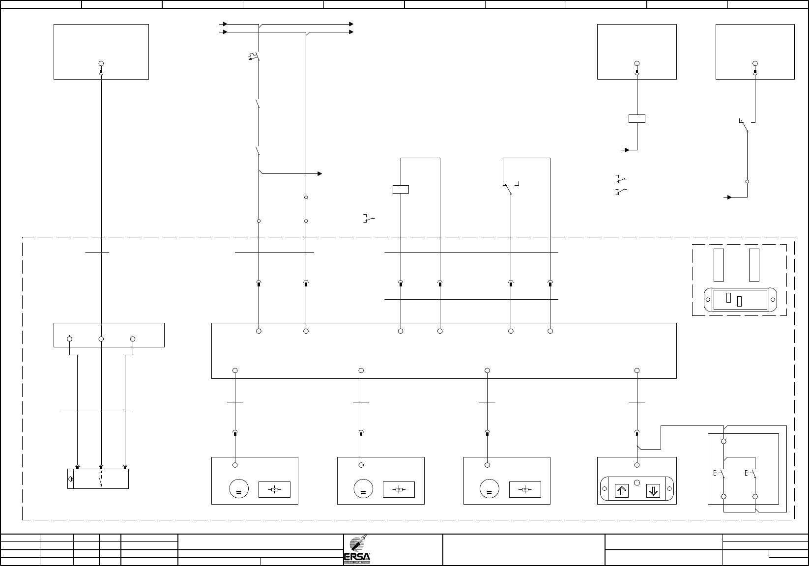
hood control
Hotflow 3/xx
PDF-Page
Plant designation
0,50
BU
0,50
BU
0,50
BU
2,50
BU
2,50
BU
2,50
BU
-24WM1
Kaufteil
0,00
1
xx
X1
motor
X2
motor
-24WM2
Kaufteil
0,00
1
xx
-24WM3
Kaufteil
0,00
1
xx
X3
motor
-24A1
24VDC
(???)
M
-24M1
24VDC
hood motor
infeed
-24M2
24VDC
hood motor outlet
-24M3
24VDC
hood motor middle
X10
display
-24A2
24VDC
terminal hood
-24WS1
0,25
4
BN BK BU
+24VDC / RD GND / BU
/10.02 / -24V-G(2)
24VDC-Sicherungen
Haube+Antriebe
/10.02 / -GND-G(2)
-24F1
B16A
supply hood-control
2
1
-22K5
/30.03
24VDC
emergency stop
connecter 1 hood
24VDC/16A
1
2
-22K6
/30.04
24VDC
emergency stop
connecter 2 hood
24VDC/16A
2
1
-GND-X5.3 / /45.00
/70.02
/75.02
/80.02
/85.02
/50.03
/55.03
/60.03
/90.02
/100.02
/105.02
/95.02
/405.04
Ground
Haube+Antriebe
-1
-X5.3
-2
-24XM1
11
-24XM2
11
-24XM3
11
2
-X5.3
RD
-24XA1
11
BU
22
-24WA1
Kaufteil
2,50
3
BN BU
-A1
X20DM9324
8xDI / 4xDO
/10.04
hood closed
IF6.ST1.DI.05
13
-24WA2
Kaufteil
0,00
1
xx
-24XA2
11
-A3
X20DO9322
12xDO
/65.06
interlocking hood
-24K1
12
11
14
.06
22
2124
/115.08
A1
A2
/30.09 / -GND-K
X8:4.1
A
X8:3.1
GND
X8:1.1
24V
-A2
SAC-box
outlet
-WA2
Kaufteil
0,25
19
VT
-24S1
hood switch
hood closesd =1
+
-
1 2 3
X7:10
Alarm/24V
X7:15
(???)
-A1
X20DM9324
8xDI / 4xDO
/10.04
hood control OK
-24K2
12
11
14
.09
A1
A2
-24K2
.04
hood control OK
12
11
14
/10.05 / -24V-X5
+15
-X5
-24WA1.2
Kaufteil
0,00
15
WH
PK WHYE BNGN
hood control OK
IF6.ST1.DI.04
22
-24XA1.1
1515 1010
M M
-24WA1.1
Kaufteil
0,00
1
xx
=HF
+E1
J2
J1
172934/0
magnetic ag
wh
bl
bk
or
bn
rd
ye
gn
vi
gy
J1
J2
-24V-G(2) / /10.02
hood interlocking
IF6.ST3.DO.03
12
-22K6:1 / /35.07
X7:1
(???)
X7:2
(???)
11 22
-24K1
.07
interlocking hood
12
11
14
13
14
-24S2
24VDC
hood
open /
close
GY
VI
WH
13
14
0 1 2 3 4 5 6 7 8 9