Plan_HF3_14_20_en line 1电路.pdf - 第34页
Pag e = C1 HF =HF +C 1/121 120 Modificati on Date Na m e op tion 2D-Sc No rm Check. Proj. Origin Date Crea. f. schb ERSA DIC 01 .0 2. 201 0 14. 04 .2 010 schb =HF +C 1/115 133 953- V00 Ot to-Schott-Straße 5 97 87 7 W ert…
Page
=
C1
HF
=HF+C1/120
115
Modification Date
Name Norm
Check.
Proj.
Origin
Date
Crea. f.
schb
ERSA
DIC
18.06.2009
=HF+C1/110
133953-V00
Otto-Schott-Straße 5
97877 Wertheim
GmbH
Project name
14:15:0708.07.2010
+
file name (*.pdf)
133953-V00_100705
basic-project
-
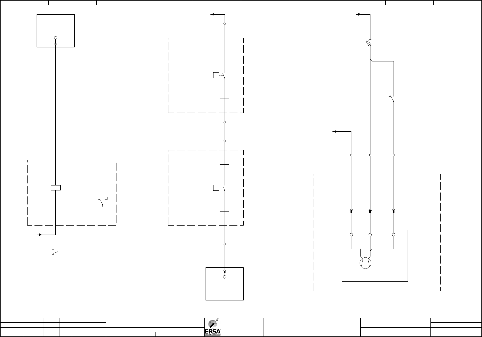
exhaust air customer;
exhaust air control infeed/outlet solder plant
Hotflow 3/xx
PDF-Page
Plant designation
0,50
BU
0,50
BU
BU
1,001,00
BU
BU
1,00
/30.09 / -GND-K
24VDC
exhaust air on
-21K1
12
11
14
.02
A1
A2
-21K1
.01
24VDC
exhaust air on
Kontakt für Abluft-
steuerung des Kunden
250VAC/10A
12
11
14
-21B1
Einstellwert: 1,2mbar / 0,2mbar
pressure switch
exhaust air infeed
P
1 = BN
3 = BU
-21B2
Einstellwert: 1,2mbar / 0,2mbar
pressure switch
exhaust air outlet
P
1 = BN
3 = BU
-21WB1
Kaufteil
0,25
4
BN
-21WB2
Kaufteil
0,25
4
BN
-21WB1
Kaufteil
0,25
4
BK
-21WB2
Kaufteil
0,25
4
BK
/10.05 / -24V-X5
+6
-X5
6
-X5
7
-X5
8
-X5
-A1
X20DM9324
8xDI / 4xDO
/10.04
-A1
X20DM9324
8xDI / 4xDO
/10.04
IF6.ST1.DI.02
exhaust air o.K.
21
exhaust air release
IF6.ST1.DO.01
15
=HF
+E1
=HF
+E1
M
1
=
-
+
=HF
+E1
-21M1
exhaust-air-flap
hood exhaust
+C1.07
1/-
2/+ 3/+
/10.09 / -GND-X5
/10.06 / -24V-G(1)
-21F1
2,5AT
supply
exhaust-air-flap
2
1
-72
-X5
37 38
-21X1
11 22 33
-21WM1
SIHF
1,00
4
321
-24K1
/40.07
interlocking hood
22
21
24
0 1 2 3 4 5 6 7 8 9
Page
=
C1
HF
=HF+C1/121
120
Modification Date
Name
option 2D-Sc
Norm
Check.
Proj.
Origin
Date
Crea. f.
schb
ERSA
DIC
01.02.201014.04.2010
schb
=HF+C1/115
133953-V00
Otto-Schott-Straße 5
97877 Wertheim
GmbH
Project name
14:15:0708.07.2010
+
file name (*.pdf)
133953-V00_100705
basic-project
-
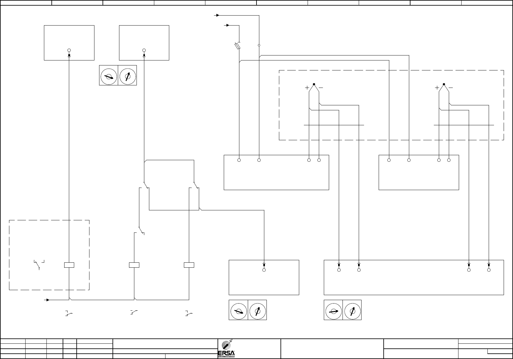
option change profile control
Hotflow 3/xx
PDF-Page
Plant designation
0,50
BU BU
0,50
BU
0,50
BU
0,50
0,50
BU
0,50
BU
BU
0,50
BU
0,50
BU
0,50
BU
0,50
BU
0,50
BU
0,50
/30.09 / -GND-K
24VDC
exhaust air on
-31K1
12
11
14
.00
A1
A2
-31K1
.01
24VDC
exhaust air on
Kontakt für Abluft-
steuerung des Kunden
250VAC/10A
12
11
14
-31A1
150°C
thermostat
excaust air infeed
=HF
+E1
L+
L- 4 5
-31B1
temperatur
excaust air infeed
12
24VDC
adjusting drive on
-31K2
12
1114
/121.01
A1
A2
/10.09 / -GND-X5
/10.06 / -24V-G(1)
24VDC-Sicherungen
SPS+Diverse
-31F2
2,0AT
supply therm ostat
2
1
-31WB1
Thermo
0,22
4
1/GN
1/WH
2/GN
2/WH
-19
-X5
-A9
X20DO9322
12xDO
/65.07
excaust air 2 on
IF6.ST9.DO.07
14
X1
C
D
B
E
A
F
9
0
8
1
7
2
6
3
5
4
X16
C
D
B
E
A
F
9
0
8
1
7
2
6
3
5
4
-A21
Adr.21
X20DM9324
8xDI / 4xDO
adjusting drive on
IF6.ST21.DO.04
26
-A21
Adr.21
X20DM9324
8xDI / 4xDO
.02
IF6.ST21.DI.04
temperatur exhaust air to high
22
-A20
Adr.20
X20AT6402
6x thermo
X1
C
D
B
E
A
F
9
0
8
1
7
2
6
3
5
4
X16
C
D
B
E
A
F
9
0
8
1
7
2
6
3
5
4
X1
C
D
B
E
A
F
9
0
8
1
7
2
6
3
5
4
X16
C
D
B
E
A
F
9
0
8
1
7
2
6
3
5
4
IF6.ST20.AT.05
exhaust air infeed
temperatur
15 16
-31A1
.04
150°C
thermostat
excaust air infeed
3
1
2
SP = 150
SEn = tc.H
-31WB2
Thermo
0,22
4
1/GN
1/WH
2/GN
2/WH
-31B2
temperature
exhaust air outlet
12
IF6.ST20.AT.04
exhaust air outlet
temperature
23 24
-31A2
150°C
thermostat
excaust air outled
L+
L-
SP = 150
SEn = tc.H
4 5
-31A2
.07
150°C
thermostat
excaust air outled
3
1
2
24VDC
adjusting drive on
-31K3
12
11
14
.02
A1
A2
-31K3
.03
24VDC
adjusting drive on
12
11
14
0 1 2 3 4 5 6 7 8 9
Page
=
C1
HF
=HF+C1/125
121
Modification Date
Name Norm
Check.
Proj.
Origin
Date
Crea. f.
schb
ERSA
DIC
01.02.2010
=HF+C1/120
133953-V00
Otto-Schott-Straße 5
97877 Wertheim
GmbH
Project name
14:15:0708.07.2010
+
file name (*.pdf)
133953-V00_100705
basic-project
-
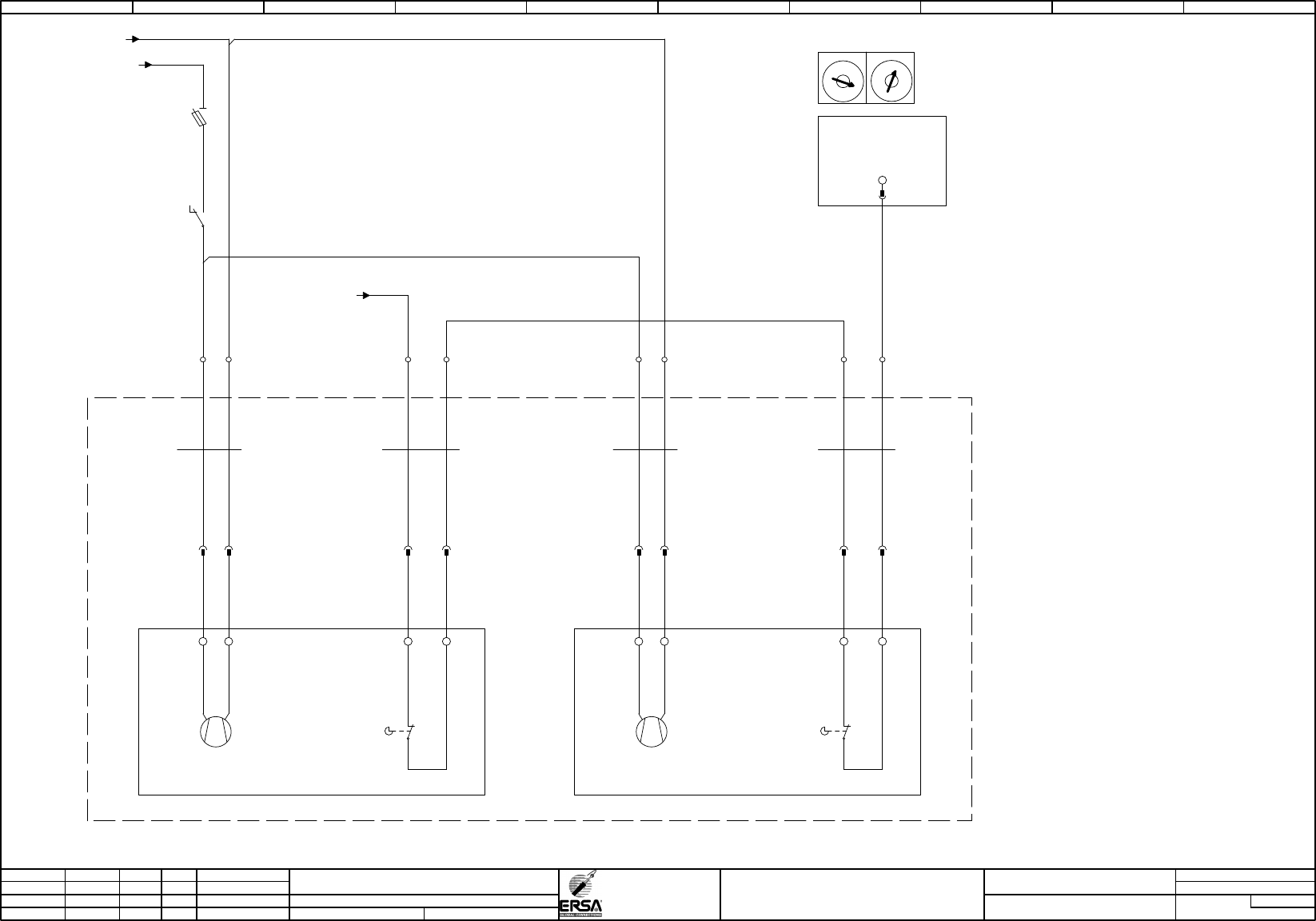
option change profile drives
Hotflow 3/xx
PDF-Page
Plant designation
BU
1,00
BU
1,00
BU
0,50
=HF
+E1
-31M1
adjusting drive top side
+C1.01
+C1.03
1 = open
0 = closed
-31WM1
SIHF
1,50
3
BN BU
-31K2
/120.02
24VDC
adjusting drive on
12
11
14
-31F1
6,3AT
supply adjusting drive
2
1
2
Supply lead drive top side
-31XM1
11
-5
M
1
=
+
-
1
22
4
/10.05 / -24V-X5
-31WM1.1
SIHF
0,75
2
BN BU
X1
adjusting drive top side
C
D
B
E
A
F
9
S1
Supply lead
limit switch drive top side
-31XM1.1
11
0
8
1
7
2
6
3
5
4
X16
C
D
B
E
S2
22
-7
A
F
9
0
8
1
7
2
6
3
5
4
-A21
Adr.21
X20DM9324
8xDI / 4xDO
/120.02
drives close
IF6.ST21.DI.03
12
/10.09 / -GND-X5
/10.06 / -24V-G(1)
-31M2
adjusting drive bottom side
+C1.04
+C1.06
1 = open
0 = closed
-31WM2
SIHF
1,50
3
BN BU
2
Supply lead drive bottom side
-31XM2
11
M
1
=
+
-
1
22
-31WM2.1
SIHF
0,75
2
BN BU
adjusting drive bottom side
S1
Supply lead
limit switch drive bottom side
-31XM2.1
11
S2
22
5
-X5
10+10 11 12
0 1 2 3 4 5 6 7 8 9