Plan_HF3_14_20_en line 1电路.pdf - 第53页
Pag e = C1 HF =HF +C 1/215 210 Modificati on Date Na m e No rm Check. Proj. Origin Date Crea. f. schb ERSA DIC 18 .0 6. 200 9 =HF +C 1/205 133 953- V00 Ot to-Schott-Straße 5 97 87 7 W ertheim Gm bH Pr oj e c t name 14:15…
Page
=
C1
HF
=HF+C1/210
205
Modification Date
Name Norm
Check.
Proj.
Origin
Date
Crea. f.
schb
ERSA
DIC
18.06.2009
=HF+C1/200
133953-V00
Otto-Schott-Straße 5
97877 Wertheim
GmbH
Project name
14:15:1008.07.2010
+
file name (*.pdf)
133953-V00_100705
basic-project
-
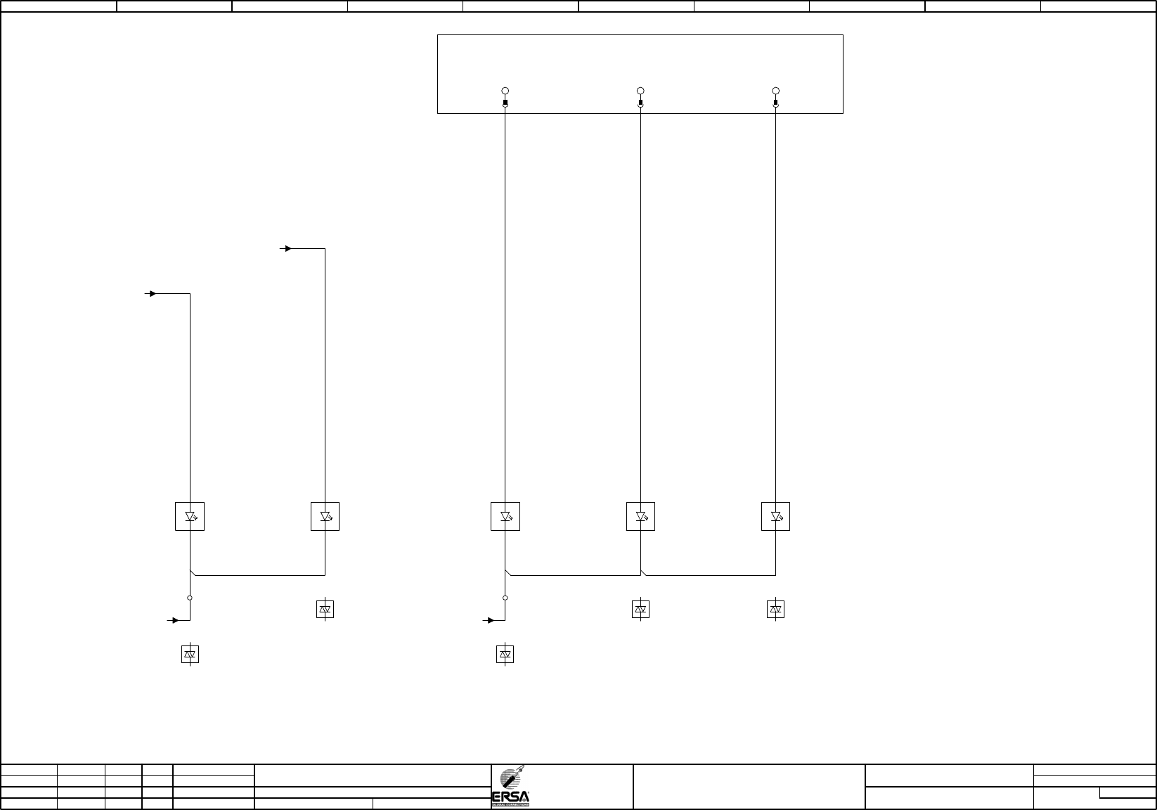
input signal solder zone bottom
Hotflow 3/xx
PDF-Page
Plant designation
BU
0,50
BU
0,50
0,50
BU
0,50
BU
0,50
BU
BU
0,50
0,50
BU
BU
0,50
BU
0,50
BU
0,50
24VDC
soldering zone
6 bottom side
-4U6
T1
L1
1
2
/320.01
+
-
A1
A2
24VDC
soldering zone
8 bottom side
-4U8
T1
L1
1
2
/330.01
+
-
A1
A2
24VDC
soldering zone
9 bottom side
-4U9
T1
L1
1
2
/335.01
+
-
A1
A2
24VDC
soldering zone
10 bottom side
-4U10
T1
L1
1
2
/340.01
+
-
A1
A2
-A3
X20DO9322
12xDO
/65.06
heating zone 8 bottom side
semiconductor relay
IF6.ST3.DO.10
25
heating zone 9 bottom side
semiconductor relay
IF6.ST3.DO.11
16
heating zone 10 bottom side
semiconductor relay
IF6.ST3.DO.12
26
/10.09 / -GND-X5 /10.09 / -GND-X5
-59
-X5
/195.07 / -A4:IF6.ST4.DO.11
/195.08 / -A4:IF6.ST4.DO:12
24VDC
soldering zone
7 bottom side
-4U7
T1
L1
1
2
/325.01
+
-
A1
A2
-63
0 1 2 3 4 5 6 7 8 9
Page
=
C1
HF
=HF+C1/215
210
Modification Date
Name Norm
Check.
Proj.
Origin
Date
Crea. f.
schb
ERSA
DIC
18.06.2009
=HF+C1/205
133953-V00
Otto-Schott-Straße 5
97877 Wertheim
GmbH
Project name
14:15:1008.07.2010
+
file name (*.pdf)
133953-V00_100705
basic-project
-
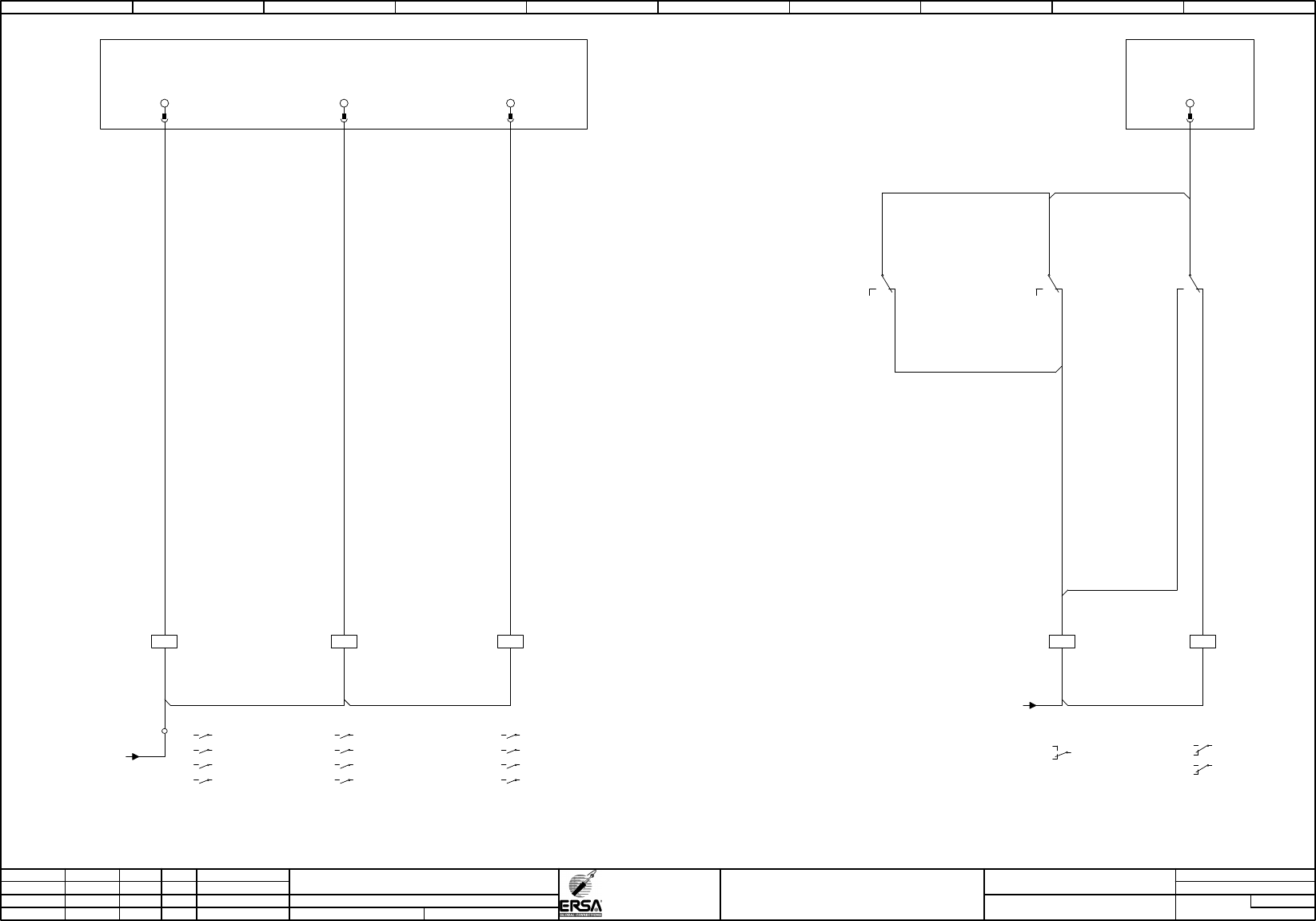
heating conacter activate
overtemp. switch off
switch on fans
Hotflow 3/xx
PDF-Page
Plant designation
BU
0,50
BU
0,50
BU
0,50
BU
0,50
0,50
BU
BU
0,50
BU
0,50
0,50
BU
0,50
BU
BU
0,50
0,50
BU
0,50
BU
0,50
BU
24VDC
heating contactor
activated
-K1
12
1114
/215.01
22
2124
/215.07
A1
A2
/30.09 / -GND-K
-A3
X20DO9322
12xDO
/65.06
heating contactor on
IF6.ST3.DO.07
14
24VDC
switch on
fan preheating
bottom side switched
-1K3
1 2
/225.07
3 4
/225.07
5 6
/225.07
7 8
A1
A2
24VDC
switch on
fan preheating zone
bottom side switched
-9K3
1 2
/285.07
3 4
/285.07
5 6
/285.07
7 8
A1
A2
24VDC
switch on
fan cooling zone
switched
-7K3
1 2
/350.01
3 4
/350.01
5 6
/350.01
7 8
/375.01
A1
A2
/10.09 / -GND-X5
-58
-X5
-A3
X20DO9322
12xDO
/65.06
fan top switched on
IF6.ST3.DO.04
22
fan bottom side switch on
IF6.ST3.DO.05
13
fan cooling zone switch on
IF6.ST3.DO.06
23
switch off
heating contactor
-38K2
12
11
14
.09
A1
A2
-38K2
.08
switch off
heating contactor
12
11
14
-38K3
/370.06
owertemp. OK
cooling zone
12
11
14
-38K1
/175.06
Overtemp. ok
heating zone 1-7
12
11
14
0 1 2 3 4 5 6 7 8 9
Page
=
C1
HF
=HF+C1/220
215
Modification Date
Name Norm
Check.
Proj.
Origin
Date
Crea. f.
schb
ERSA
DIC
18.06.200926.07.2004
=HF+C1/210
133953-V00
Otto-Schott-Straße 5
97877 Wertheim
GmbH
Project name
14:15:1008.07.2010
+
file name (*.pdf)
133953-V00_100705
basic-project
-
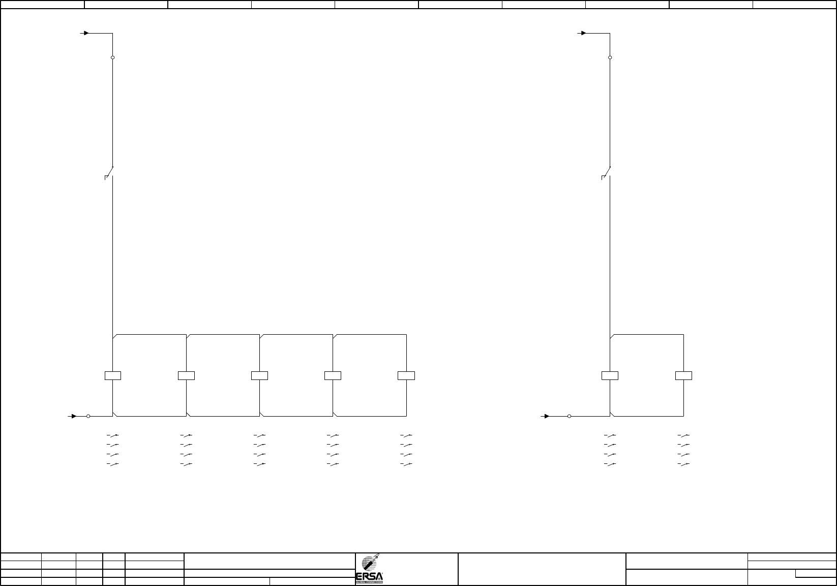
heating contactor activated
Hotflow 3/xx
PDF-Page
Plant designation
BU
0,50
0,50
BU
BU
0,50
BU
0,50
0,50
BU
0,50
BU
0,50
BU
BU
0,50
0,50
BU
BU
0,50
BU
0,50
BU
0,50
BU
0,50
BU
0,50
BU
0,50
BU
0,50
/10.09 / -GND-X5
/10.05 / -24V-X5
-K1
/210.09
24VDC
heating contactor
activated
22
21
24
24VDC
soldering zone
top on
-3K1
1 2
/260.02
3 4
/265.02
5 6
/270.02
7 8
/275.02
A1
A2
24VDC
soldering zone
bottom side on
-4K1
1 2
/320.02
3 4
/325.02
5 6
/330.02
7 8
/335.02
A1
A2
/10.09 / -GND-X5
/10.05 / -24V-X5
-K1
/210.09
24VDC
heating contactor
activated
12
11
14
24VDC
preheating zone
zone 1-4 top on
-1K1
1 2
/225.02
3 4
/230.02
5 6
/235.02
7 8
/240.02
A1
A2
24VDC
preheating zone
zone 5-7 top on
-1K2
1 2
/245.02
3 4
/250.02
5 6
/255.02
7 8
/280.02
A1
A2
24VDC
preheating zone
1-4 bottom side on
-9K1
1 2
/285.02
3 4
/290.02
5 6
/295.02
7 8
/300.02
A1
A2
24VDC
preheating zone
5-7 bottom side on
-9K2
1 2
/305.02
3 4
/310.02
5 6
/315.02
7 8
/340.02
A1
A2
+11
-X5
+12
-21
-X5
-23
-X5
24VDC
cooling zone
heating on
-7K1
1 2
/370.01
3 4
5 6
7 8
A1
A2
0 1 2 3 4 5 6 7 8 9