Plan_HF3_14_20_en line 1电路.pdf - 第85页
Pag e = C1 HF =HF +C 1/375 370 Modificati on Date Na m e No rm Check. Proj. Origin Date Crea. f. schb ERSA DIC 18 .0 6. 200 9 26. 07 .0 204 =HF +C 1/365 133 953- V00 Ot to-Schott-Straße 5 97 87 7 W ertheim Gm bH Pr oj e …
Page
=
C1
HF
=HF+C1/370
365
Modification Date
Name Norm
Check.
Proj.
Origin
Date
Crea. f.
schb
ERSA
DIC
18.06.200921.09.2006
=HF+C1/360
133953-V00
Otto-Schott-Straße 5
97877 Wertheim
GmbH
Project name
14:15:1408.07.2010
+
file name (*.pdf)
133953-V00_100705
basic-project
-
supply frequency inverter
fan heating zone 1-7 + cooling zone
Hotflow 3/xx
PDF-Page
Plant designation
BK
2,50
BK
2,50
BK
2,50
GNYE
2,50
BK
2,50
BK
2,50
BK
2,50 2,50
GNYE BK
2,50
BK
2,50
BK
2,50 2,50
GNYE BK
2,50
BK
2,50
BK
2,50 2,50
GNYE BK
2,50
BK
2,50
BK
2,50 2,50
GNYE
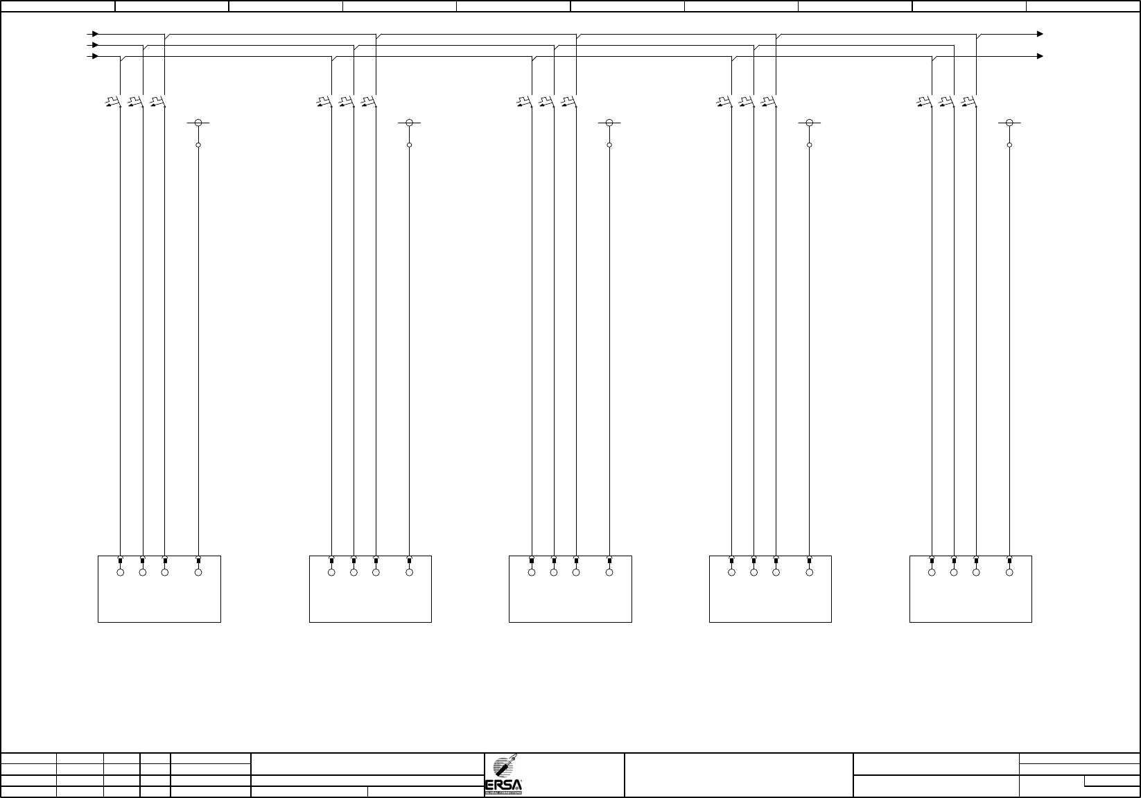
/350.01 / -L1-Q1
/350.01 / -L2-Q1
/350.01 / -L3-Q1
PE6
-X2
PE7 PE8
PE-C1 PE-C1 PE-C1
-1A1
3,0kW
frequency inverter
fan preheating top
-7A1
1,1kW/3,0kW
frequency inverter
fan cooling zone
L1 L2
PE PE
-9A1
3,0kW
frequency inverter
fans preheating bottom side
PE
-3A1
1,1kW
frequency inverter
fans soldering zone top
PE-C1
PE
-4A1
1,1kW
frequency inverter
fans soldering zone
bottom side
PE-C1
PE
-L3-Q1 / /20.06
-L1-Q1 /
PE9 PE10
-1F11
K20A
frequency inverter
fans preheating top
2
1
4
3
6
5
-9F11
K20A
frequency inverter
fan preheating bottom side
2
1
4
3
6
5
-7F11
K16A/K20A
frequency inverter
fan cooling zone
2
1
4
3
6
5
-3F11
K16A
frequency inverter
fan soldering top
2
1
4
3
6
5
-4F11
K16A
frequency inverter
fan soldering bottom side
2
1
4
3
6
5
L3 L1 L2 L3 L1 L2 L3 L1 L2 L3 L1 L2 L3
HF3/14; HF3/20 with out cooling bottom "152422"
HF3/20 with cooling bottom "152424"
0 1 2 3 4 5 6 7 8 9
Page
=
C1
HF
=HF+C1/375
370
Modification Date
Name Norm
Check.
Proj.
Origin
Date
Crea. f.
schb
ERSA
DIC
18.06.200926.07.0204
=HF+C1/365
133953-V00
Otto-Schott-Straße 5
97877 Wertheim
GmbH
Project name
14:15:1408.07.2010
+
file name (*.pdf)
133953-V00_100705
basic-project
-
controled cooling zone
Hotflow 3/xx
PDF-Page
Plant designation
2,50
BK
2,50
BK
2,50
BK
2,50
BK
BU
0,50
BU
0,50
BU
0,50
BU
0,50
BU
0,50
0,50
BU
BU
0,50
BU
0,50
BU
0,50
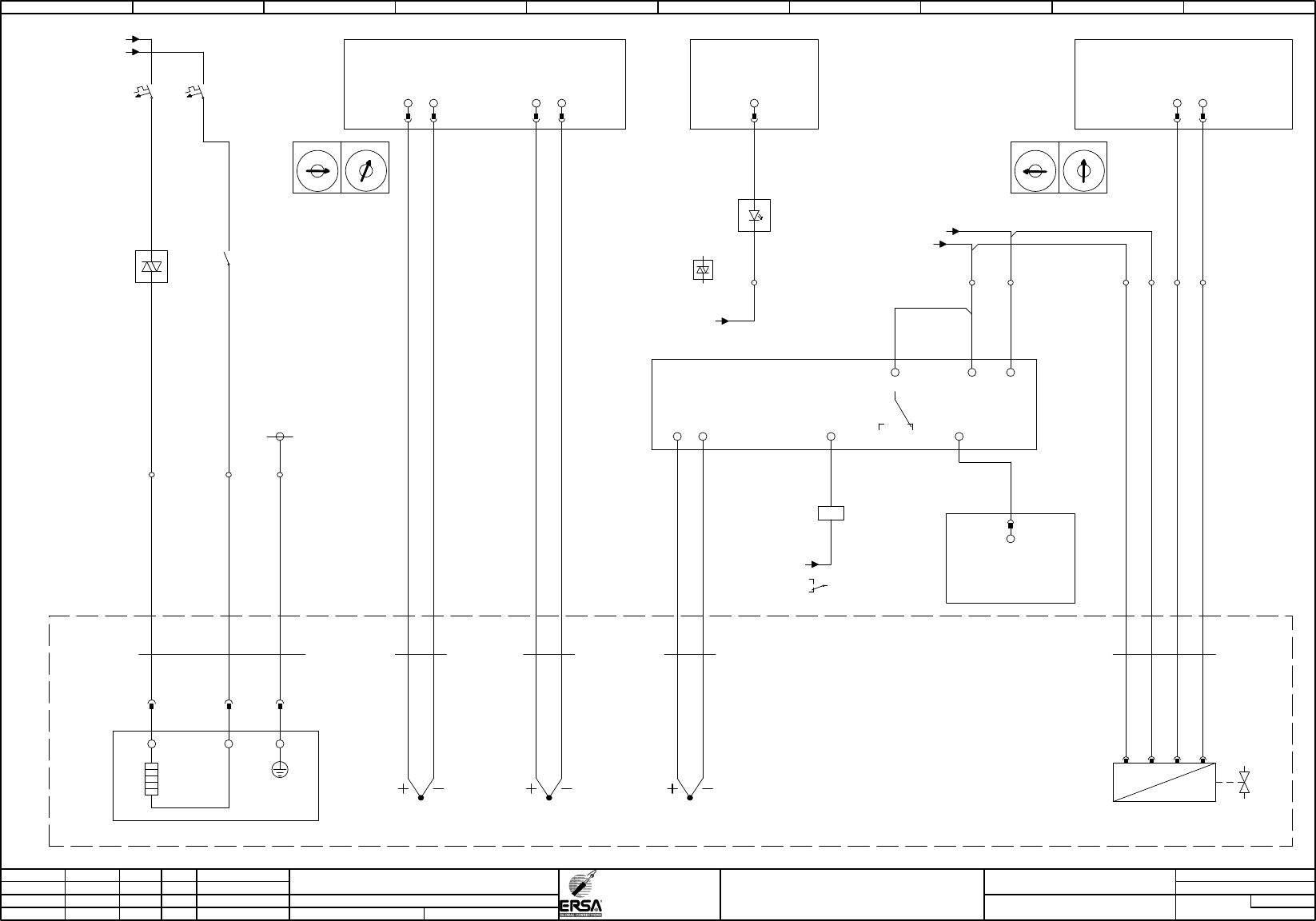
=HF
+CM
-7E1
3,3kW/400V
heating
cooling zone
/340.08 / -10F2:1 (L1)
-7WE1
Kaufteil
2,50
3
BN BU
GNYE
L
-7XE1
11
L
22
PE-C1
PE
33
1
-7X2.1
2
PE2
-7F1
B16A
heating cooling zone
2
1
4
3
-A3
X20DO9322
12xDO
/65.06
controled cooling zone
semiconductor relay
IF6.ST3.DO.08
24
/10.09 / -GND-X5
-38
-X5
heating cooling zone
-7U1
T1
L1
L1
T1
.01
+
-
A1
A2
-7U1
.05
heating cooling zone
T1
L1
L1
T1
-7K1
/215.04
24VDC
cooling zone
heating on
1
2
-A12
Adr.12
X20CM8281
4xDI/2xDO/1xAI/1xAO
/415.08
flow recuperator cooling zone
IF6.ST12.AO.01.2
2526
X1
C
D
B
E
A
F
9
0
8
1
7
2
6
3
5
4
X16
C
D
B
E
A
F
9
0
8
1
7
2
6
3
5
4
/10.05 / -24V-X5
/10.09 / -GND-X5
39+39
-77
-A20
Adr.20
X20AT6402
6x thermo
/120.06
X1
C
D
B
E
A
F
9
0
8
1
7
2
6
3
5
4
X16
C
D
B
E
A
F
9
0
8
1
7
2
6
3
5
4
-7WB10
Thermo
0,22
2
GN
WH
-7B10
thermoelement
recuperator flow
GN
WH
-7WY1
Kaufteil
0,25
4
BN
WH
BU BK
-7A11
650°C
thermostat
controled cooling zone
L+
L-
4 5
-7B1.1
thermoelement
cooling zone 1 top
GN1
WH1
-7WB1.1
Thermo
0,22
2
GN
WH
SP = 650
SEn = tc.H
+38
-75
0-10 V
proportional valve
controled cooling zone
-7Y1
A
P
1 2 3 4
40
cooling zone temperature
recuperator flow
IF6.ST20.AT.01
11 12
-7WB11
Thermo
0,22
2
GN
WH
-7B11
thermoelement
recuperator return
GN
WH
cooling zone temperature
recuperator return
IF6.ST20.AT.02
21 22
/340.08 / -10F2:3 (L2)
1
2 3
owertemp. OK
cooling zone
-38K3
12
11
14
/210.06
A1
A2
/30.09 / -GND-K
-A12
Adr.12
X20CM8281
4xDI/2xDO/1xAI/1xAO
/415.08
IF6.ST12.DI.02
cooling zone
exceed temperatur
21
0 1 2 3 4 5 6 7 8 9
Page
=
C1
HF
=HF+C1/380
375
Modification Date
Name Norm
Check.
Proj.
Origin
Date
Crea. f.
schb
ERSA
DIC
18.06.2009
=HF+C1/370
133953-V00
Otto-Schott-Straße 5
97877 Wertheim
GmbH
Project name
14:15:1408.07.2010
+
file name (*.pdf)
133953-V00_100705
basic-project
-
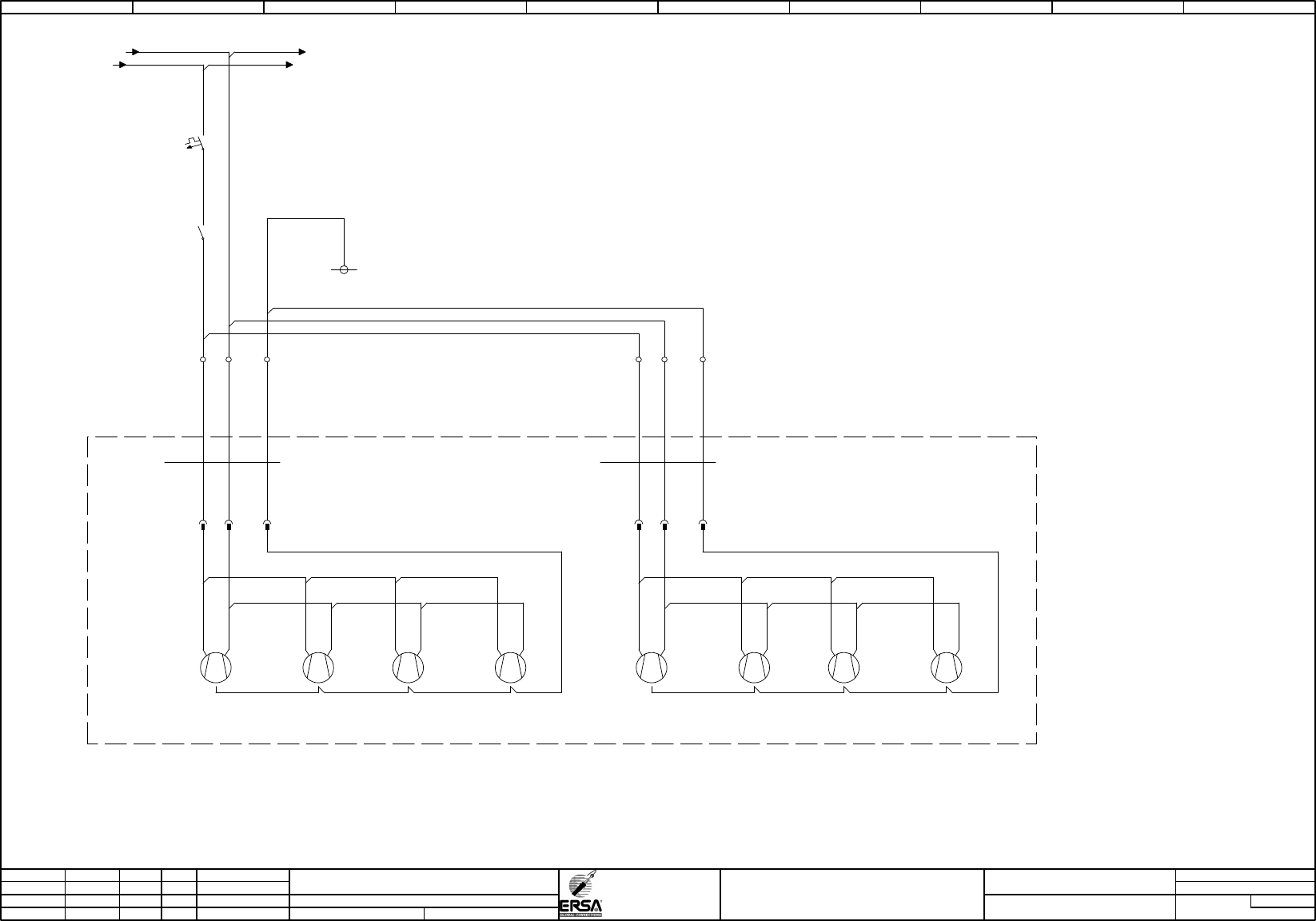
outlet cooling
Hotflow 3/xx
PDF-Page
Plant designation
BK
1,50
BK
1,50
BK
0,75
BK
0,75
BK
0,75
BK
1,00
BK
1,00
BK
1,00
-7M10
outlet cooling
transverse -fan
M
1
~
1 2
-7M11
outlet cooling
transverse -fan
M
1
~
1 2
-7M12
outlet cooling
transverse -fan
M
1
~
1 2
-7M13
outlet cooling
transverse -fan
M
1
~
1 2
-7F10
B6A
outlet cooling
2
1
=HF
+CM
/125.01 / -N -N / /395.02
11
-X2
N11 PE11
PE-C1
-7M20
outlet cooling
axial-fan
M
1
~
1 2
-7M21
outlet cooling
axial-fan
M
1
~
1 2
-7M24
outlet cooling
axial-fan
M
1
~
1 2
-7M25
outlet cooling
axial-fan
M
1
~
1 2
12
N12 PE12
-7WM10
SIHF
0,75
3
outlet cooling
transverse -fan
BN BU
GNYE
-7WM20
H05VV5-F
0,75
3
outlet cooling
axial-fan
1 2 GNYE
-7XM20
11 22
PEPE
-7XM10
11 22
PEPE
/5.06 / -22K4:5 (L3) -22K4:5 (L3) / /380.06
-7K3
/210.03
24VDC
switch on
fan cooling zone
switched
7
8
0 1 2 3 4 5 6 7 8 9