00196932-02 SM S-Feeder Repair DE+EN multilang.pdf - 第110页
6 Checking and adjusting 3x8mm, 12-88mm S-Feeder 6.4 3x8mmS: Checking cover strip removal motor, track 1, 2 & 3 current input 110 SIPLACE S-Feeder Repair SIPLACE S-Förderer Reparatur 3. Turn the switch 1 (Track 1) up…
6 Checking and adjusting 3x8mm, 12-88mm S-Feeder
6.4 3x8mmS: Checking cover strip removal motor, track 1, 2 & 3 current input
SIPLACE S-Feeder Repair SIPLACE S-Förderer Reparatur 109
6.4
6.4 3x8mmS: Checking cover strip removal motor, track 1, 2 & 3 current input
3x8mmS: Checking cover strip removal motor, track 1, 2 & 3 cur
-
rent input
3. Turn the switch 1-3 upwards.
4. Check the direction of rotation of stuffing gear (in the
illustration, the lowest gear range). The gears must rotate
in the direction of the arrow.
5. With the 5/30V switch you can turn the wheels fast or
slow. The 30V setting is suitable for endurance tests
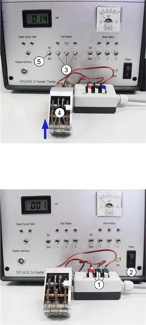
1. Set switches 1-3 in "Foil motor" in the lower position
and insert the cover strip disposal motor unit to the exten
-
sion box. Track 1 (red) on the connector 1, track 2 (green)
on the connector 2 and 3 track 3 (blue) on the Connector
3
2. Switch on the S-Feeder Motor Tester. Set the 5/30V
switch under "foil motor" up (5V). The 30V switch position
is suitable for endurance test.
6 Checking and adjusting 3x8mm, 12-88mm S-Feeder
6.4 3x8mmS: Checking cover strip removal motor, track 1, 2 & 3 current input
110 SIPLACE S-Feeder Repair SIPLACE S-Förderer Reparatur
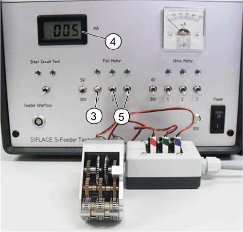
3. Turn the switch 1 (Track 1) upwards.
4. Read the current consumption. The setpoint is 4-8 mA.
5. Perform the test with track 2 and 3 (switches 2 and 3).
Check out that always just one track is turned on.
7 3x8mm S-Feeder checking and adjusting worm gear
7.1 Overview: 3x8mmS worm gear test set
SIPLACE S-Feeder Repair SIPLACE S-Förderer Reparatur 111
7
7 3x8mm S-Feeder checking and adjusting worm gear
3x8mm S-Feeder checking and adjusting worm
gear
7.1
7.1 Overview: 3x8mmS worm gear test set
Overview: 3x8mmS worm gear test set
7.2
7.2 3x8mmS: Adjusting current input via the worm play
3x8mmS: Adjusting current input via the worm play
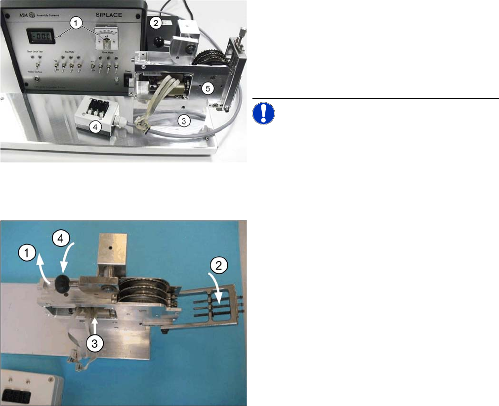
1. S-Feeder Motor Testbox with display of the current
consumption
2. Power supply
3. Adjustment for the worm game.
4. Extern junction box
5. 3x8mmS worm gear
NOTICE! The worm drive clearance is adjusted
by means of the adjusting device such that the rated cur
-
rent input value is being reached (measured with the test
-
er).
1. Swing the lever (black handle) upward.
2. Fold the track-adjusting jig downward.
3. Insert the drive assembly into the jig from the side.
The two centering pins of the drive assembly must slide
into the holes of the device!
4. Swing the lever (black handle) downward in order to ar
-
rest the drive assembly.