00196932-02 SM S-Feeder Repair DE+EN multilang.pdf - 第111页
7 3x8mm S-Feeder checking and adjusting w orm gear 7.1 Overview: 3x8mmS worm gear test set SIPLACE S-Feeder Repair SIPLACE S-Förderer Reparatur 111 7 7 3 x 8 m m S - F e e d e r c h e c k in g a n d a d ju s t in g w o r…
6 Checking and adjusting 3x8mm, 12-88mm S-Feeder
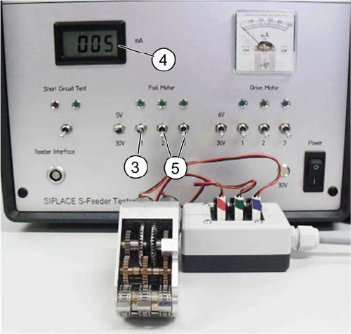
6.4 3x8mmS: Checking cover strip removal motor, track 1, 2 & 3 current input
110 SIPLACE S-Feeder Repair SIPLACE S-Förderer Reparatur
3. Turn the switch 1 (Track 1) upwards.
4. Read the current consumption. The setpoint is 4-8 mA.
5. Perform the test with track 2 and 3 (switches 2 and 3).
Check out that always just one track is turned on.
7 3x8mm S-Feeder checking and adjusting worm gear
7.1 Overview: 3x8mmS worm gear test set
SIPLACE S-Feeder Repair SIPLACE S-Förderer Reparatur 111
7
7 3x8mm S-Feeder checking and adjusting worm gear
3x8mm S-Feeder checking and adjusting worm
gear
7.1
7.1 Overview: 3x8mmS worm gear test set
Overview: 3x8mmS worm gear test set
7.2
7.2 3x8mmS: Adjusting current input via the worm play
3x8mmS: Adjusting current input via the worm play
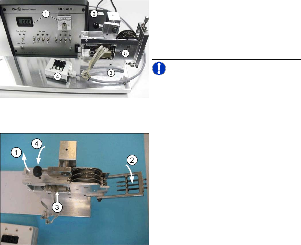
1. S-Feeder Motor Testbox with display of the current
consumption
2. Power supply
3. Adjustment for the worm game.
4. Extern junction box
5. 3x8mmS worm gear
NOTICE! The worm drive clearance is adjusted
by means of the adjusting device such that the rated cur
-
rent input value is being reached (measured with the test
-
er).
1. Swing the lever (black handle) upward.
2. Fold the track-adjusting jig downward.
3. Insert the drive assembly into the jig from the side.
The two centering pins of the drive assembly must slide
into the holes of the device!
4. Swing the lever (black handle) downward in order to ar
-
rest the drive assembly.
7 3x8mm S-Feeder checking and adjusting worm gear
7.2 3x8mmS: Adjusting current input via the worm play
112 SIPLACE S-Feeder Repair SIPLACE S-Förderer Reparatur
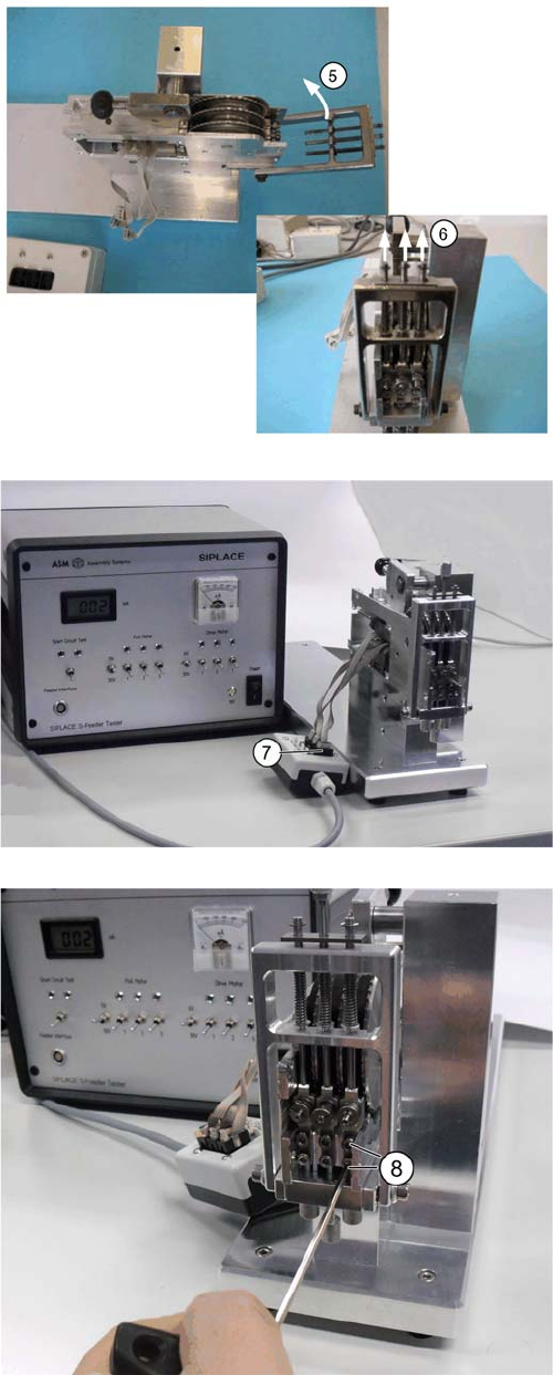
5. When in upper position, fold up the adjustable flap and
...
6. ... pull up the three pressing pins in the upper position
in order to fold the jig completely upward.
7. Heed the labeling (blue,green, red) and connect the
three motor cables to the connection box using the cor
-
rect color assignment.
Red → black connector 1
Green → black connector 2
Blue → black connector 3
Now the drives of the three tracks will be checked and ad
-
justed in consecutive order from left to right.
8. Loosen the two Allen screws (size 2.5) of the drive unit,
starting with the left track..