00196932-02 SM S-Feeder Repair DE+EN multilang.pdf - 第116页
8 2x8mm S-Feeder checking and replace wo rm gear 8.1 Removing Sprocket Wheel / Worm Gea r 116 SIPLACE S-Feeder Repair SIPLACE S-Förderer Reparatur 6. Remove the hex screw (M5), holding the sprocket wheel. 7. Open the und…
8 2x8mm S-Feeder checking and replace worm gear
8.1 Removing Sprocket Wheel / Worm Gear
SIPLACE S-Feeder Repair SIPLACE S-Förderer Reparatur 115
8
8 2x8mm S-Feeder checking and replace worm gear
2x8mm S-Feeder checking and replace worm gear
8.1
8.1 Removing Sprocket Wheel / Worm Gear
Removing Sprocket Wheel / Worm Gear
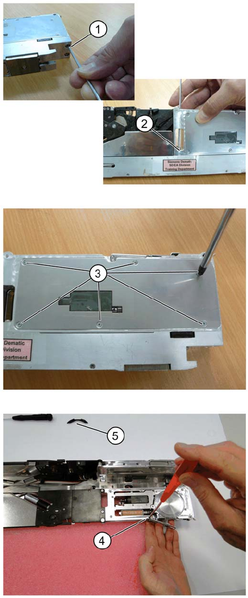
Remove the M2.5 screw on base of the respective front
track at location
1. On the front under site of the feeder.
2. From the top in the middle of the base plate.
3. Remove six countersunk screws on each side of the
track.
4. Remove the pickup window.
5. Remove the protection ring.
8 2x8mm S-Feeder checking and replace worm gear
8.1 Removing Sprocket Wheel / Worm Gear
116 SIPLACE S-Feeder Repair SIPLACE S-Förderer Reparatur
6. Remove the hex screw (M5), holding the sprocket
wheel.
7. Open the under cover above the control pcb.
8. Remove three M2.5 screws
9. Disconnect all connectors (qty : 03) on the PCB
10. Slide out the drive motor unit upwards, down from the
guide pin.
11. Remove sprocket wheel assembly using a pin punch.
8 2x8mm S-Feeder checking and replace worm gear
8.2 Design of Sprocket Wheel
SIPLACE S-Feeder Repair SIPLACE S-Förderer Reparatur 117
8.2
8.2 Design of Sprocket Wheel
Design of Sprocket Wheel
8.3
8.3 Design Worm Drive
Design Worm Drive
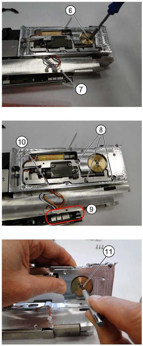
1. Position oblong marking at 12 o’clock, as shown.
2. Use a permanent marker to highlight the position, as
shown.
3. Position brass gear orientation mark in line with dur
-
ing assembly.
1. pre-assembled driving wheel SII 00326684S01
2. protection ring 00315131S02
3. Bearing face (x2) 00326663-01
4. Running disk for Axial cage 00326596-01
5. Feeder plate 24.7X15.4X0.4 plated 00327189-01
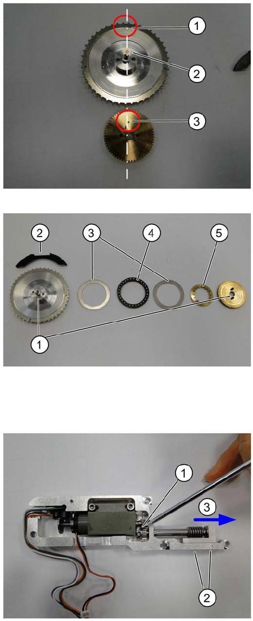
1. Loosen the M1.5 screw at the drive shaft
2. Remove both M2 screws at the bottom of the drive
motor unit.
3. Slide out drive shaft, together with the bearing block
SII..