00196932-02 SM S-Feeder Repair DE+EN multilang.pdf - 第122页
9 3x8mm S-Feeder Transport moto r exchange 9.2 Drive motor assembly 122 SIPLACE S-Feeder Repair SIPLACE S-Förderer Reparatur 1. Place the new motor 2. Fix th e moter loo sely wi th the two mounting screws. 1. Route the c…
9 3x8mm S-Feeder Transport motor exchange
9.2 Drive motor assembly
SIPLACE S-Feeder Repair SIPLACE S-Förderer Reparatur 121
9.2
9.2 Drive motor assembly
Drive motor assembly
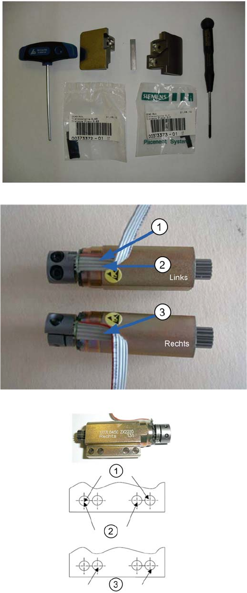
Required tools for assembly
▪ Allen key 2.5
▪ Waterproofed coloured pencil (green/blue/red)
▪ Distance plate 0,7mm
▪ Distance plate 0,63 mm
▪ Safety plate right/middle
▪ Safety plate left
▪ Crosshead screwdriver (small)
▪ Label the connectors:
1 = Red (left track)
2 = Green (middle track)
3 = Blue (right track)
▪ Bend the cables according to the motor position.
▪ Use the demounted motor as sample.
▪ For the left and middle track a motor labled „Left“ will
be used!
The following drill holes are used for fixation of motors:
1. Screws for drive motor middle.
2. Screws for drive motor left.
3. Screws for drive motor right.
9 3x8mm S-Feeder Transport motor exchange
9.2 Drive motor assembly
122 SIPLACE S-Feeder Repair SIPLACE S-Förderer Reparatur
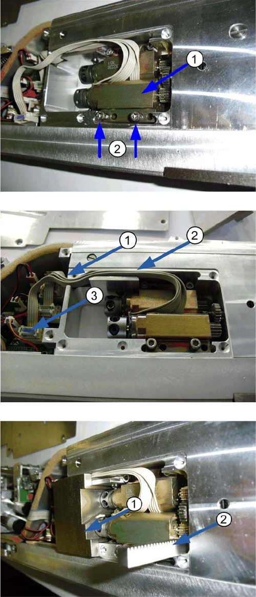
1. Place the new motor
2. Fix the moter loosely with the two mounting screws.
1. Route the cable
2. Connect the motor to the corresponding socket on
the control!
1. Insert the appropriate safety plate. This protects
against mechanical damages to the motor!
2. Slide the toothed rack under the motor gear pinion.
Turn the motor shaft. Observe the limit pin.
9 3x8mm S-Feeder Transport motor exchange
9.3 Following tasks
SIPLACE S-Feeder Repair SIPLACE S-Förderer Reparatur 123
9.3
9.3 Following tasks
Following tasks
Set up the pick-up position with the S-Feeder Test Station (SFTS).
Check the pickup position of all tracks with the SFTS and then mount the motor cover. Read the corre
-
sponding instructions for SFTS.
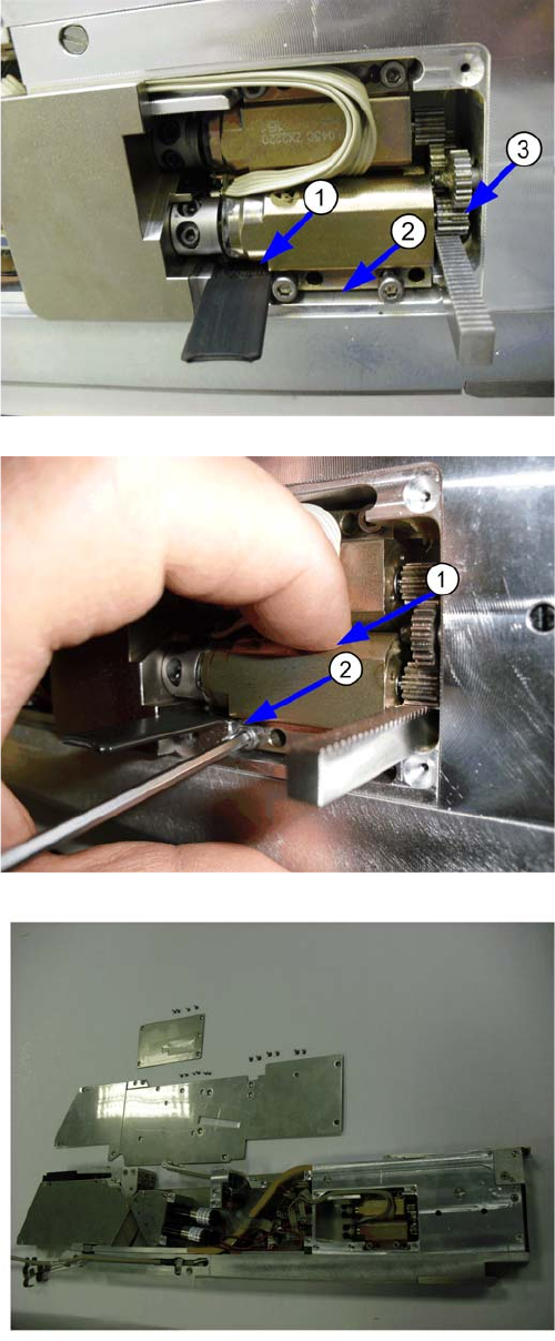
1. Insert the appropriate adjust gauge under the rear
part of the motor. 003773373-01 adjust gauge
0,7mm for motor " right and middle track".
003773372-01 adjust gauge 0,63mm for "left track"
2. By the toothed rack and the adjustment gauge, the
distance between feeder housing and motor will be
set.
3. The two gear wheels are well positioned to one an
-
other.
1. Lightly press the motor on the adjust gauge and the
toothed rack
2. Mount the motor with two screws.
▪ Remove the toothed rack, adjust gauge and safety
plate.
▪ Assemble the side panel of the feeder.
▪ The motor cover is mounted only after setting the
pick-up position.
▪ If this is to be carried out later then please mount the
motor cover, in order to avoid the soiling and the loss
of components.
▪ The installation of the motor is completed.