西门子SIPLACE HS 60-设备参数_EN - 第11页
9 Placement Heads: Nozzle Changer for 12-Nozzle Collect & Place Head (Option) Technical Data Type of nozzle All standard nozzles of nozzle series 9xx C ap ac it y 5 magazines holding 12 nozzles a each per changer max…
8
Placement Heads:
12-Nozzle Collect & Place Head
for Very High Speed Component Placement
Technical Data
Stroke of Z-axis max. 16 mm
Programmable placement force 2.4 to 5.0 N
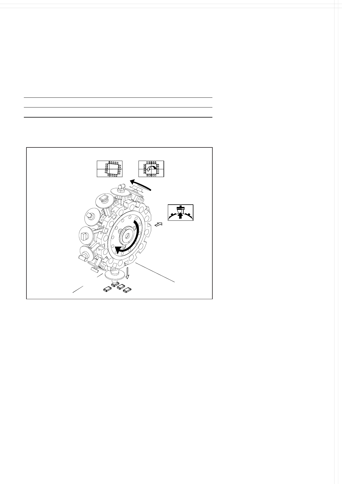
12-Nozzle Collect & Place Head for Very High Speed Placement
Component Pick-Up/
Placement
Segment
Removal
Point
Turning to
the Placement
Position
Component
Vision
Description
The 12-Nozzle placement head
operates on the Collect & Place
principle. The 12 vacuum nozzles
of the SIPLACE Collect & Place
Head rotate around a horizontal
axis. In addition to space savings
this offers the following benefits:
Due to the small diameter the
centrifugal forces are significantly
lower. The results are high-speed,
reliable placement and the same
cycle time for all components.
Components are picked up and
placed reliably with the aid of vac-
uum followed by a gentle air kiss.
A number of vacuum tests moni-
tors if the component has been
picked up and placed accurately.
Various control and self-learning
functions further enhance the de-
pendability of the system:
The optical recognition of feeder
positions records the exact po-
sition of the feeder table.
A camera on the placement head
(component vision module) de-
termines the exact position of
each component on the nozzle.
For every feeder the pick-up
offsets are averaged over the
last ten pick-ups. This enables
the head to dial-in on the pre-
cise pick point for each compo-
nent.
In addition, the package form is
also checked. If the actual geo-
metric dimensions of the com-
ponent do not correspond to
those programmed, the compo-
nent is rejected.
Components rejected by the vi-
sion system are dumped into a
bin, reject feeder or matrix tray.
Any rejected component gets
automatically placed during a
repair run.
Warpage of the PCB is accom-
modated by sensor stop acti-
vated z-axis placement. The sys-
tem also keeps the last ten
positions of the z-axis at com-
ponent placement and uses the
average of these values to im-
prove the drive down and place
speed of the cycle.
To check very small compo-
nents, such as 0201, it is helpful
to use a component sensor.
This infra-red sensor checks the
presence of components before
pick-up and placement, ensuring
reliable handling of even the
smallest components.
9
Placement Heads:
Nozzle Changer for 12-Nozzle Collect & Place Head (Option)
Technical Data
Type of nozzle All standard nozzles of nozzle series 9xx
Capacity 5 magazines holding 12 nozzles
a
each per changer
max. 2 nozzle changers per placement head
Nozzle changing time About 2 s per nozzle
a) Nozzles can be of different types.
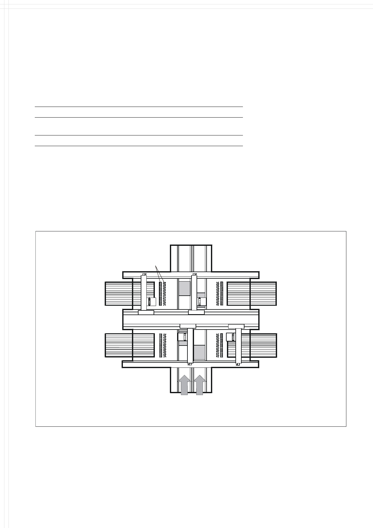
Description
A maximum of 2 nozzle changers
can be installed for each of the
12-Nozzle Collect & Place Heads,
which allows for 120 unique noz-
zles per Collect & Place Head
without decreasing feeder quanti-
ties. This allows a quick and reli-
able change of the nozzle configu-
ration when changing to another
job. Damaged or faulty nozzles
can also be exchanged via menu
function.
Nozzle Changer
Position of Nozzle Changers
10
PCB Conveyor:
Single Conveyor
Technical Data
PCB dimensions See table on page 3
PCB thickness 0.5 to 4.5 mm
Max. PCB weight 3 kg
Max. PCB warpage Top: 4.5 mm - PCB thickness
Bottom: 0.3 mm + PCB thickness
Free space on PCB bottom side 40 mm
PCB conveyor height
830 ± 15 mm (Standard)
900 ± 15 mm (Option)
930 ± 15 mm (Option)
950 ± 15 mm (Option) SMEMA
Fixed conveyor edge Right (standard); left (option)
Type of interface Siemens (standard); SMEMA (option)
Component-free PCB
handling edge
3 mm
PCB loading time 2.5 s
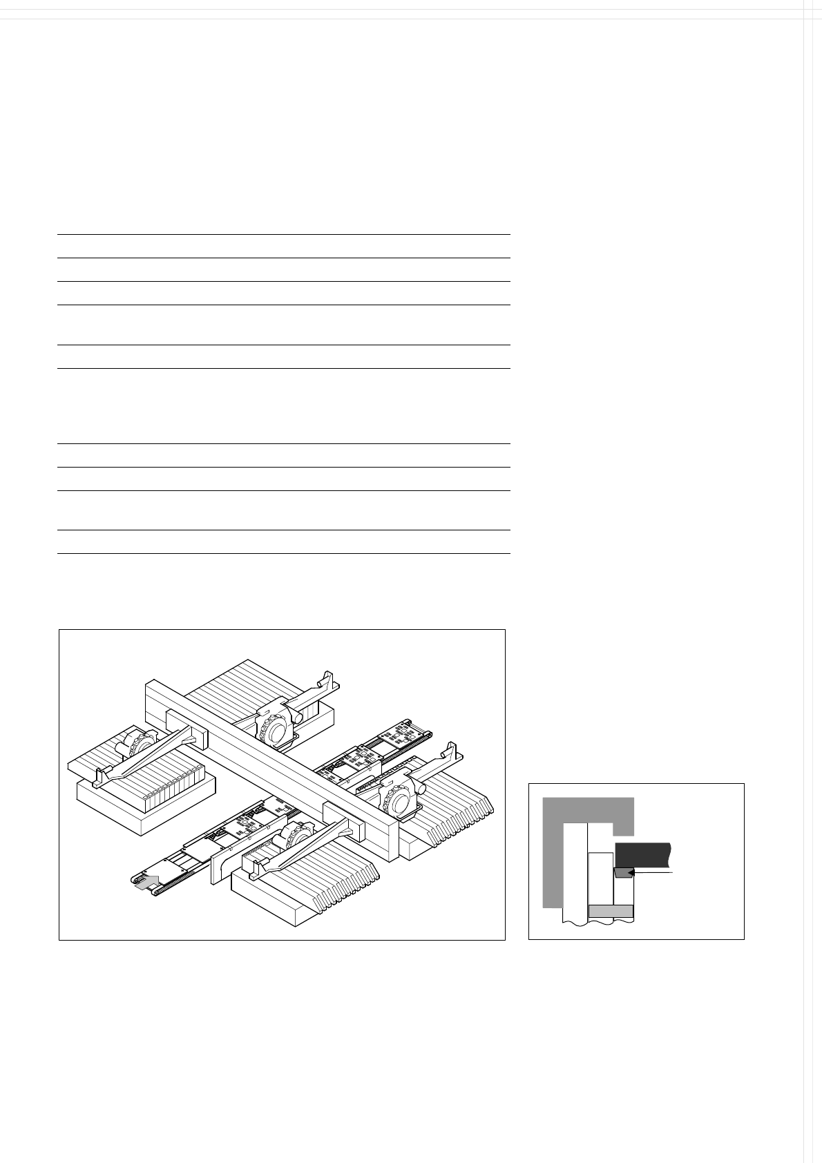
Description
On SIPLACE HS-60 the in-line
conveyor system guarantees a
quick adjustment to new PCB
widths. The change is made either
at the station computer using the
menu function or from the line
computer via the automatic width
adjustment unit.
The PCB is clamped from the
bottom to the top side of the
conveyor. This offers several
advantages:
Higher real placement rate
Robust PCB recognition (cam-
era focus point)
Shorter PCB change time
Easier change of fixed conveyor
edge right/left also in field
Quicker learning function, as the
PCB height does not effect the
Z-stroke, resulting in higher
placement rates
The conveyor can be ordered with
a fixed rail on right or left. As stan-
dard the SIPLACE placement sys-
tems are available with a single
conveyor system.
PCB Transport
Direction
PCB
Axle
Clamp
Conveyor
belt
Clamping of PCB
PCB Conveyor