西门子SIPLACE HS 60-设备参数_EN - 第12页
10 PCB Conveyor: Single Conveyor Technical Data PCB dimensions See table on page 3 PCB thickness 0.5 to 4.5 mm Max. PCB weight 3 kg Max. PCB warpage Top: 4.5 mm - PCB thickness Bottom: 0.3 mm + PCB thickness Free space o…
9
Placement Heads:
Nozzle Changer for 12-Nozzle Collect & Place Head (Option)
Technical Data
Type of nozzle All standard nozzles of nozzle series 9xx
Capacity 5 magazines holding 12 nozzles
a
each per changer
max. 2 nozzle changers per placement head
Nozzle changing time About 2 s per nozzle
a) Nozzles can be of different types.
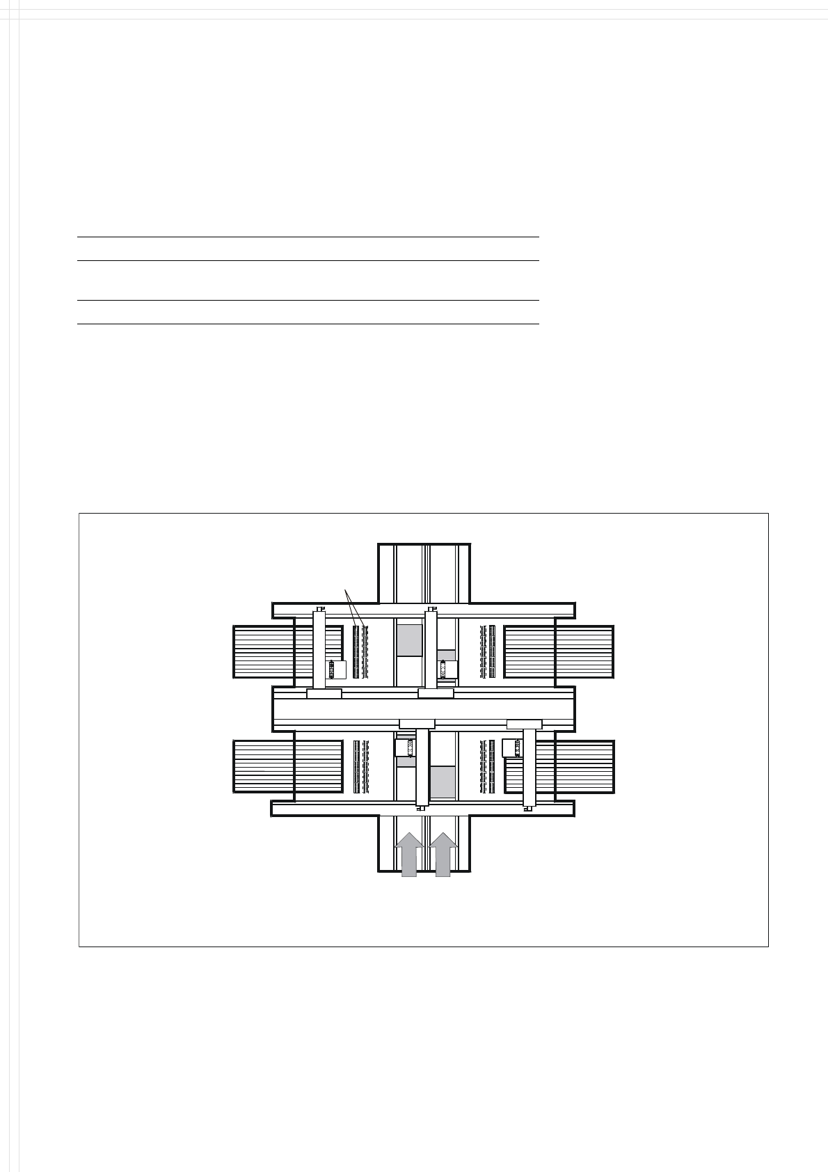
Description
A maximum of 2 nozzle changers
can be installed for each of the
12-Nozzle Collect & Place Heads,
which allows for 120 unique noz-
zles per Collect & Place Head
without decreasing feeder quanti-
ties. This allows a quick and reli-
able change of the nozzle configu-
ration when changing to another
job. Damaged or faulty nozzles
can also be exchanged via menu
function.
Nozzle Changer
Position of Nozzle Changers
10
PCB Conveyor:
Single Conveyor
Technical Data
PCB dimensions See table on page 3
PCB thickness 0.5 to 4.5 mm
Max. PCB weight 3 kg
Max. PCB warpage Top: 4.5 mm - PCB thickness
Bottom: 0.3 mm + PCB thickness
Free space on PCB bottom side 40 mm
PCB conveyor height
830 ± 15 mm (Standard)
900 ± 15 mm (Option)
930 ± 15 mm (Option)
950 ± 15 mm (Option) SMEMA
Fixed conveyor edge Right (standard); left (option)
Type of interface Siemens (standard); SMEMA (option)
Component-free PCB
handling edge
3 mm
PCB loading time 2.5 s
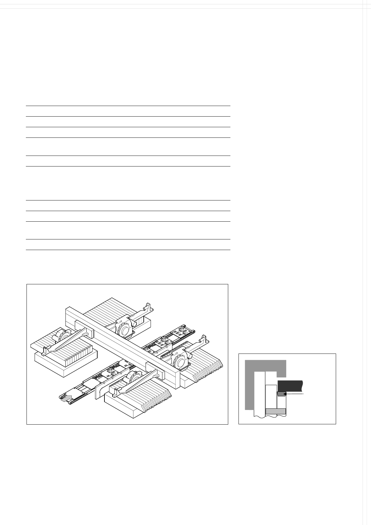
Description
On SIPLACE HS-60 the in-line
conveyor system guarantees a
quick adjustment to new PCB
widths. The change is made either
at the station computer using the
menu function or from the line
computer via the automatic width
adjustment unit.
The PCB is clamped from the
bottom to the top side of the
conveyor. This offers several
advantages:
Higher real placement rate
Robust PCB recognition (cam-
era focus point)
Shorter PCB change time
Easier change of fixed conveyor
edge right/left also in field
Quicker learning function, as the
PCB height does not effect the
Z-stroke, resulting in higher
placement rates
The conveyor can be ordered with
a fixed rail on right or left. As stan-
dard the SIPLACE placement sys-
tems are available with a single
conveyor system.
PCB Transport
Direction
PCB
Axle
Clamp
Conveyor
belt
Clamping of PCB
PCB Conveyor
11
PCB Conveyor:
Flexible Dual Conveyor
Technical Data
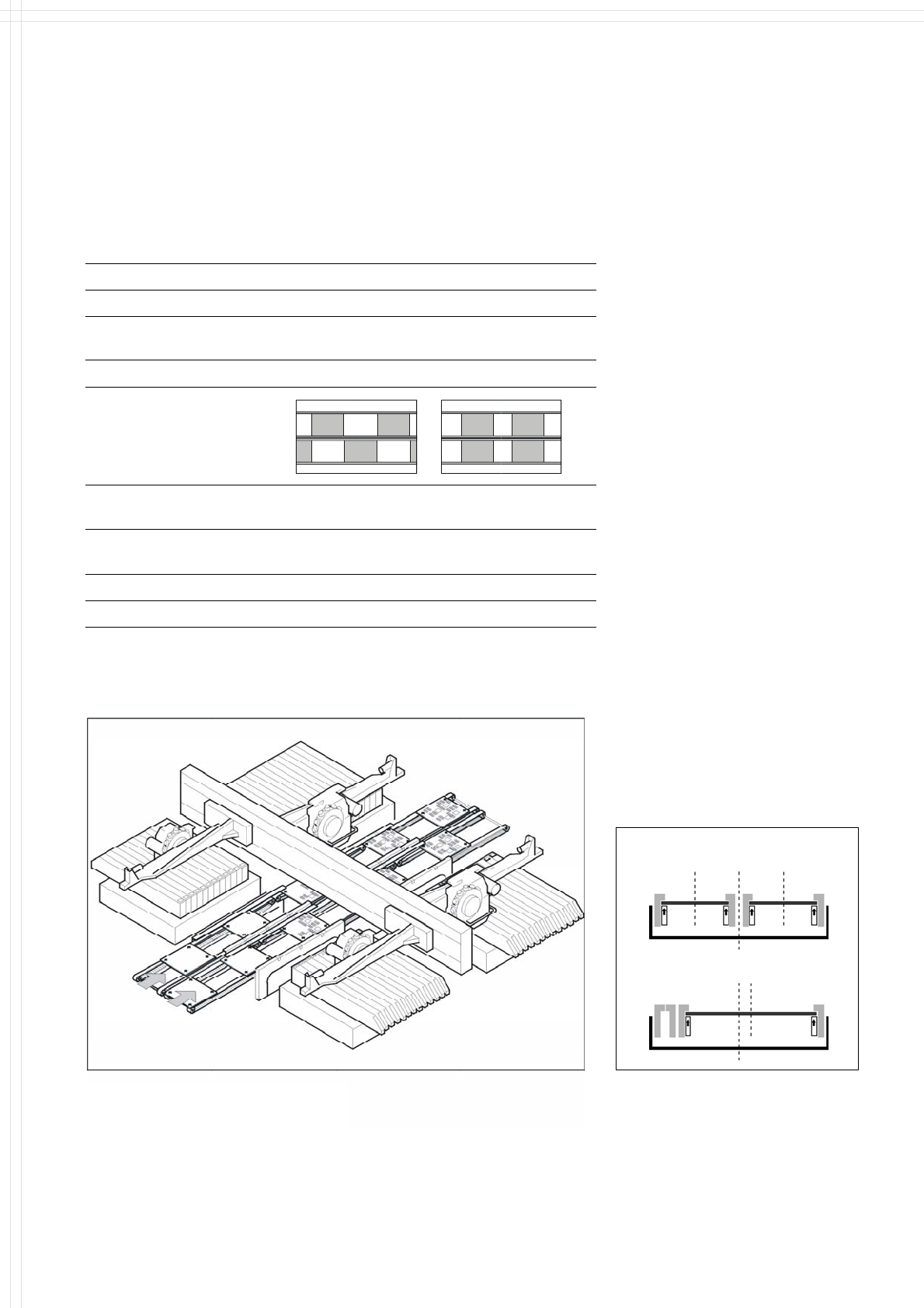
Description
Thanks to reduced non-productive
times the dual PCB conveyor can
substantially increase the through-
put, depending on the program. It
makes it possible to transport two
PCBs through the machine.
PCB dimensions See table on page 3
Fixed conveyor edge Right (standard), left (option)
Asynchronous and Synchronous Transport on Dual Conveyor
Transport mode Asynchronous Synchronous
View
Placement program
per conveyor
same or different same or different
PCB width
per conveyor
same same or different
Ink spot recognition possible not possible
Automatic width adjustment possible not possible
Asynchronous transport
A PCB is moved into the machine
in “slack time” while the other
PCB is being populated. The non-
productive time caused by the PCB
transport is completely eliminated.
The increase in placement speed
reaches 30%, depending on the
components placed on the PCB.
Synchronous transport
Two PCBs are populated simul-
tanously. The real placement rate
can be increased, especially when
boards with only a few compo-
nents are handled.
PCB
Transport Direction
By use of Station Computer Soft-
ware 505.02 (or higher) the dual con-
veyor can be processed in single
conveyor mode, which allows the
handling of PCBs with a maximum
width up to 380mm (see table on
page 3).
Modus 1: Dual Conve
y
or
Modus 2: Single Conveyor
Dual Conveyor with Asynchronous Transport
Flexible Dual Conveyor