西门子SIPLACE HS 60-设备参数_EN - 第16页
14 Component Supply: Changeover Table Technical Data Component feeder tables (exchangeable) 4 tables per machine compatible only with SIPLACE HS-60 Feeder location 12 feeders 3 x 8 mm per table = 144 tracks of 8 mm per m…
13
PCB Conveyor:
PCB Bar Code for Production-Controlled Manufacturing
(Option)
Technical Data
Label dimensions Stroke width: W: 0.19 < W ≤ 0.3 mm
(corresponds to high + medium density)
Stroke length: ≥ 4 mm a
Length of scanning window: ≤ 90 mm
Recommended
label colors
Color coding: black, dark green or dark blue
Background: white, beige, yellow, orange
(contrast ratio > 70% as per DIN 66236)
Code types Code 39, Code 128 / EAN 128, Codabar, 2/5 interleaved,
2/5 IATA 2/5 industrial, UPC, EAN, Pharma Code,
EAN Addendum (more upon request); max. 25 char-
acters, definition of a bar code filter possible
Safety of the
laser scanner
Laser diode 670 nm (red) / 1 mW
Laser protection class 2, degree of protection IP65
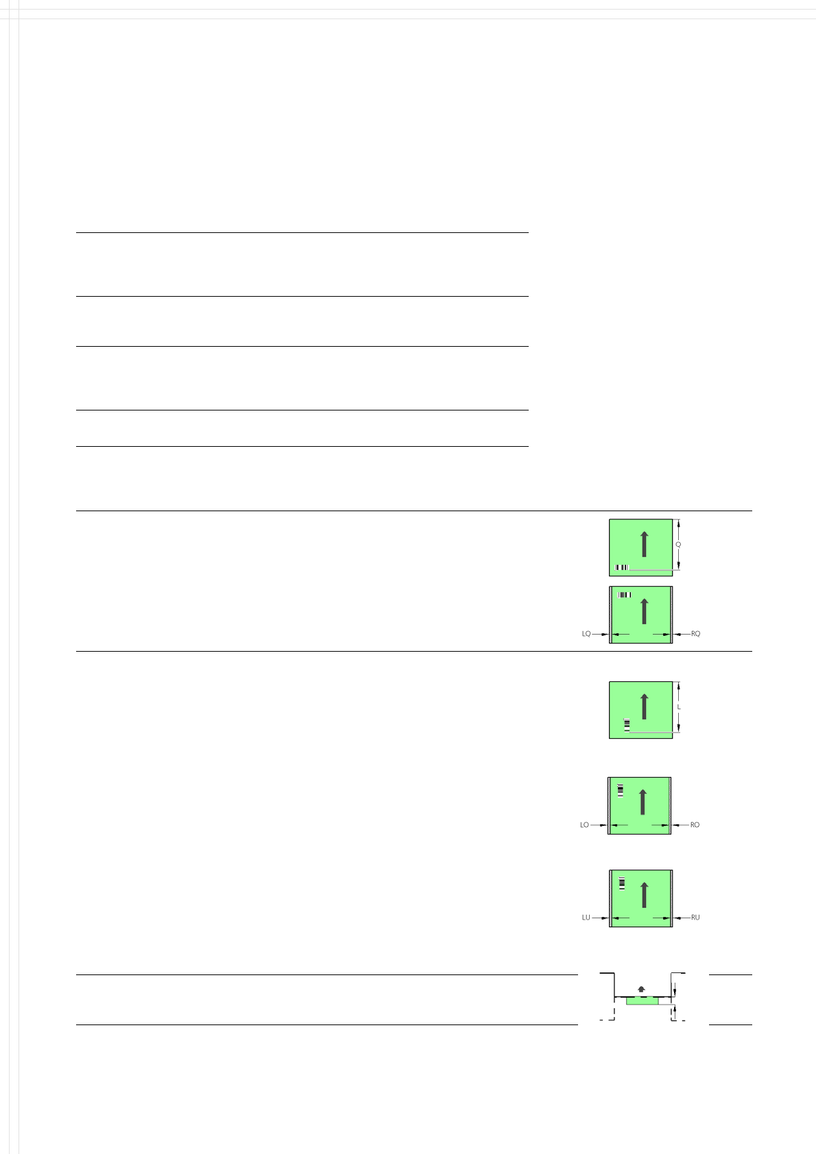
Restrictions Depending to sort of scanner (1D / 2D) as well as
orientation (along / across to transport direction) and
position of the bar code (top/bottom of PCB) distinct
distances have to be obeyed:
Bar code (BC)
ACROSS to
transport direction
Q = Distance
PCB front edge to
BC back border
RQ/LQ = Distance
PCB side edge to BC-side
border right/left
2D-scanner PCB top:
Q: max. 310 mm, RQ: min. 3 mm, LQ: min. 3 mm
2D-scanner PCB bottom:
Q: max. 310 mm, RQ: min. 5 mm, LQ: min. 5 mm
1D-scanner PCB top:
Q: max. 310 mm, RQ: min. 3 mm, LQ: min. 3 mm
1D-scanner PCB bottom:
Q: max. 310 mm, RQ: min. 5 mm, LQ: min. 5 mm
Barcode (BC)
ALONG
transport direction
L = Distance
PCB front edge to
BC back border
RO/LO = Distance
PCB side edge to BC-
side border right/left
(PCB top)
RU/LU = Distance
PCB side edge to BC-
side border right/left
(PCB bottom)
1D-scanner PCB top L: 240 - 310 mm,
• with single conveyor
standard 18" RO: min. 35 mm, LO: min. 3 mm
Option 20" RO: min. 61 mm, LO: min. 3 mm
• with dual conveyor, lane 1
standard 8,5" RO: min. 40 mm, LO: min. 3 mm
2x9,5"/1x430 RO: min. 66 mm, LO: min. 3 mm
• with dual conveyor, lane 2
standard 8,5" RO: min. 3 mm, LO: min. 3 mm
2x9,5"/1x430 RO: min. 3 mm, LO: min. 3 mm
1D-scanner PCB bottom L: 280 - 350 mm,
• with single conveyor
standard 18"/460 RU: min. 5 mm, LU: min. 35 mm
Option 20"/508 RU: min. 5 mm, LU: min. 61 mm
• with dual conveyor, lane 1
standard 8,5" RU: min. 5 mm, LU: min. 15 mm
2x9,5"/1x430 RU: min. 5 mm, LU: min. 15 mm
• with dual conveyor, lane 2
standard 8,5"/216 RU: min. 5 mm, LU: min. 40 mm
2x9,5"/1x430/250 RU: min. 5 mm, LU: min. 66 mm
Space required
for bar code in
transport direction
2D-scanner PCB bottom, lane 2
mechanical abundance over machine:
no abundance
Description
The SIPLACE PCB bar code scan-
ner supports the flexible produc-
tion of SMD products and en-
hances placement reliability. The
laser scanner reads the bar code
label on the top and/or bottom of
each PCB moving during transport.
On the basis of the bar code in-
formation the line computer auto-
matically selects the correct place-
ment program from the previously
prepared bar code assignment list
and sends it to the station.
The bar code filter can be utilized,
if only certain information con-
tained in the bar code is relevant.
14
Component Supply:
Changeover Table
Technical Data
Component feeder tables
(exchangeable)
4 tables per machine
compatible only with SIPLACE HS-60
Feeder location 12 feeders 3 x 8 mm per table =
144 tracks of 8 mm per machine
Feeder modules SIPLACE tape and bulk feeders
Accessories Tape container, waste container,
Description
SIPLACE HS-60 is equipped with
four stationary component tables,
one for each placement head.
With these four tables SIPLACE
HS-60 can accommodate a total of
144 different 8 mm part numbers.
On the changeover tables tape
feeders and Bulk Case feeders
can be positioned. For safety rea-
sons tracks not in use should be
equipped with guards for feeder
locations.
Component feeders are stationary
during the placement process.
This allows for the replenishment
of both tape and bulk components
during machine operation.
For the changeover, individual
feeders or entire changeover ta-
bles can be exchanged without
the use of tools or external lifts.
Job changeover times can be
dramatically reduced with the use
of additional feeder tables. This
will allow large set-ups to be com-
pleted off line without impacting
machine production time
Using component bar codes with
the optional Component Bar Code
Scanner guarantees the correct al-
location of component to track.
Changeover tables are equipped
with rollers and an integrated
pneumatic lifting device which
eliminates the need of an external
lifting cart as with other equip-
ment. Exchanging the tables takes
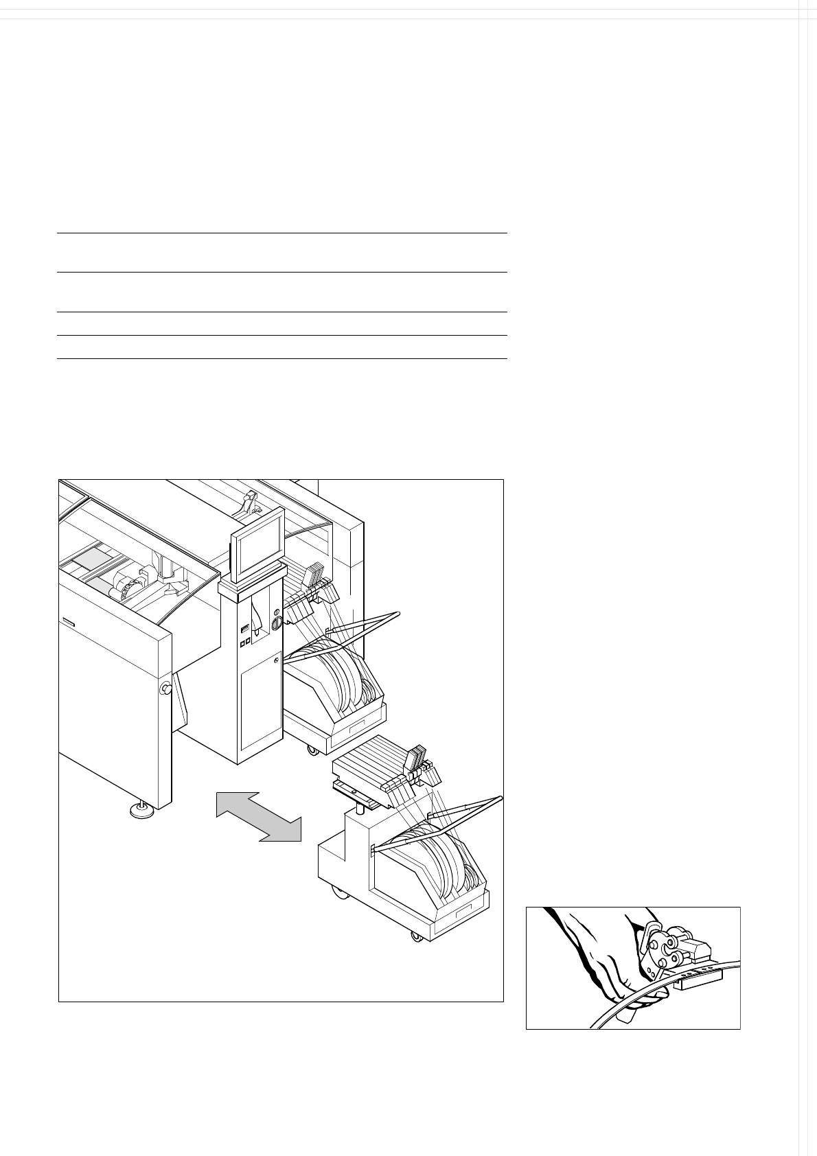
less than 2 minutes per module.
Mobile
Changeover
Table
Splicing Too
l
Exchange of a Component Changeover Table
15
Component Supply:
Tape Feeder
Technical Data
Packaging Model Feeder
locations
Transport
distance
Max. Height
of component
Paper and
blister tapes
2 x 8 mm S
a
3 x 8 mm S
3 x 8 mm S
b
12/16 mm S
1
1
1
1
2 or 4 mm
2 or 4 mm
2 mm
4 - 12 mm
c
2.5 mm
2.5 mm
0.7 mm
14 mm
Blister tape 24/32 mm S 1.5 4 - 32 mm
c
14 mm
Tape reels Ø 7" to 19" (178 - 470 mm)
a) Fiducial for recognition of position of feeders;
b) only for 0201 and 0402;
c) adjustable in increments of 4 mm.
Description
The tape reels of the feeder mod-
ules are accommodated in the
tape container of the component
changeover table. A cutter auto-
matically chops up empty tape
when it comes out.
Feeder modules used on SIPLACE
are distinguished by a short cycle
time and a highly accurate pick-up
position. The feeder pitch is easily
adjustable. Thanks to the general
purpose tape feeder modules
which are equally suitable for pa-
per and blister tapes, a small range
of module types is sufficient. This
is a decisive advantage for in-
vestment and logistics. Once acti-
vated by a signal from the compo-
nent table, the modules control
the entire feeder operation of the
automatic strip removal all by
themselves.
3 x 8 mm S
The feeders series feature very
short cycle times and they can
handle tapes with 2 mm grids
(8 mm S). 8 mm S and
12 / 16 mm S are equipped
with component cover.
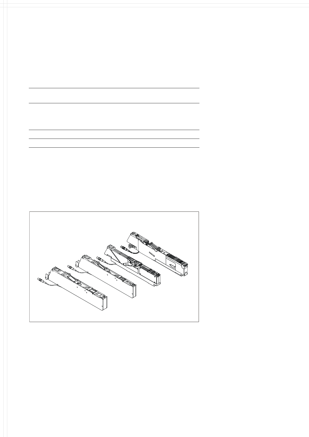
2 x 8 mm S
12 / 16 mm S
24 / 32 mm S
Tape Feeder Modules S