西门子SIPLACE HS 60-设备参数_EN - 第19页
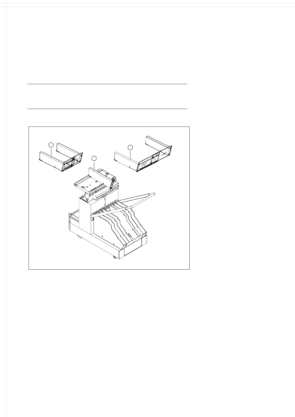
17 Component Supply: Guard for Feeder Locations The following guard-variants can be used: 1 SIPLACE guard for 1 location 2 SIPLACE guard for 6 - 10 locations 3 SIPLACE guard for 11 - 20 locations Description Some local s…
16
Component Supply:
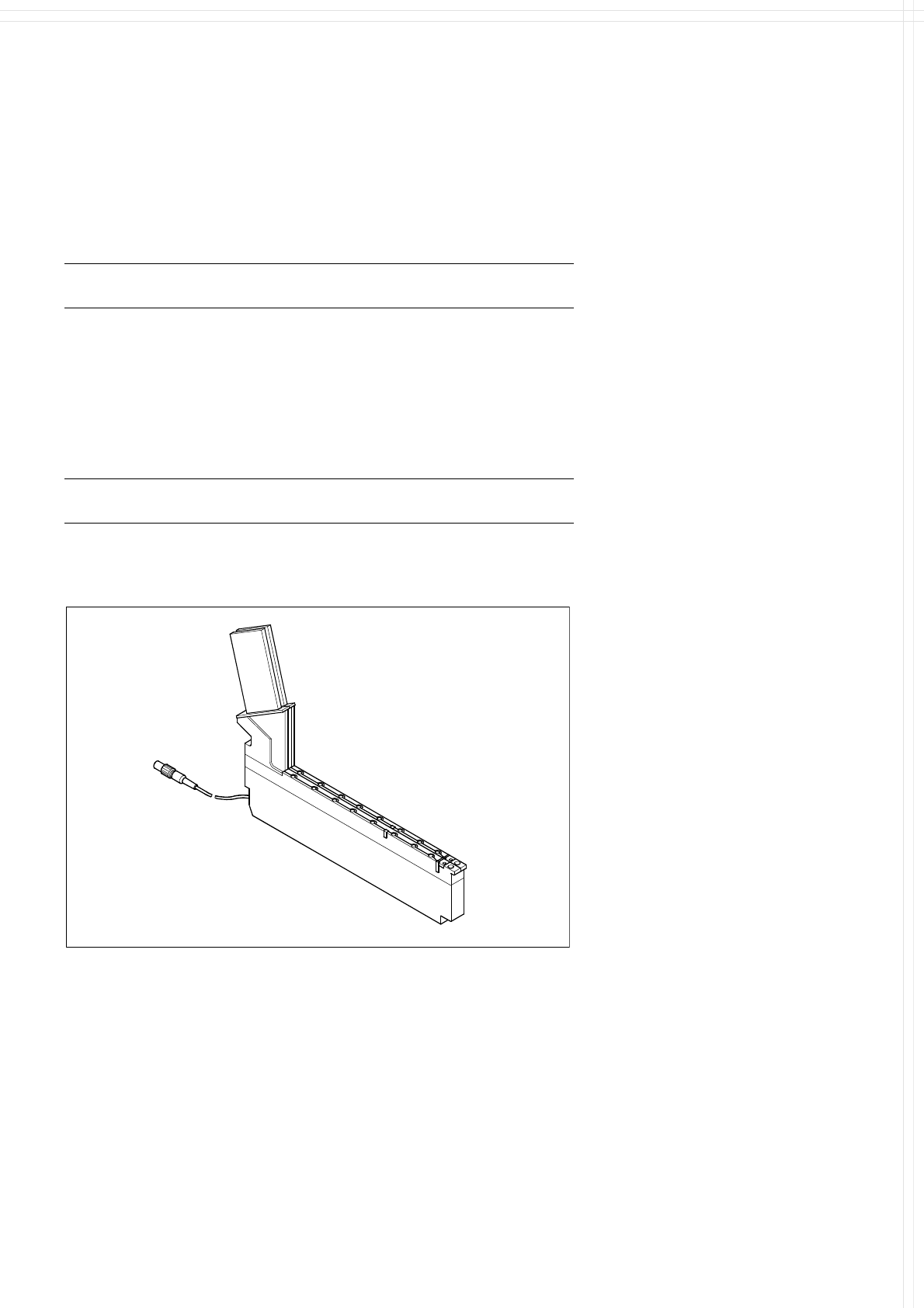
Bulk Case Feeder
Technical Data
Bulk Case feeder
a
Packaging form
Bulk Case
Feed rails for: Chip 0402 component height 0.35 mm
Chip 0402 component height 0.50 mm
Chip 0603 component height 0.45 mm
Chip 0603 component height 0.80 mm
Chip 0805 component height 0.45 mm
Chip 0805 component height 0.60 mm
Chip 0805 component height 0.85 mm
Chip 0805 component height 1.25 mm
Mini-Melf
Feeder location 1 feeder location for 2 different compo-
nent types
a) Reference mark to recognize the position of feeder.
Description
The SIPLACE Bulk Case feeder
with 2 tracks is used to handle
components packaged in standard
bulk containers. It transports rec-
tangular and cylindrical passive
components to the pick up area of
the machine. To replenish the sup-
ply, the Bulk Cases are removed
and replaced outside the machine
eliminating stoppages for replen-
ishment.
Essentially, this feeder module
consists of a base which holds 2
feeder rails. The components are
separated and transported through
the feeder rail via compressed air.
The principle of stationary compo-
nent tables has been tried and
tested specifically with Bulk Case
components. Vibrations, which
developed when other placement
methods are used may cause
wear to the components compro-
mising quality and reliability of the
components.
Bulk Case Feeder
Bulk Case Feeder
17
Component Supply:
Guard for Feeder Locations
The following guard-variants can be used:
1 SIPLACE guard for 1 location
2 SIPLACE guard for 6 - 10 locations
3 SIPLACE guard for 11 - 20 locations
Description
Some local safety requirements
dictate that all feeder locations
must be equipped with feeders.
If the feeder set-up does not fill all
feeder locations, guards may be
used in place of the modules.
1
3
2
SAFETY
WARNING
Various Guards for Feeder Locations
18
Component Supply:
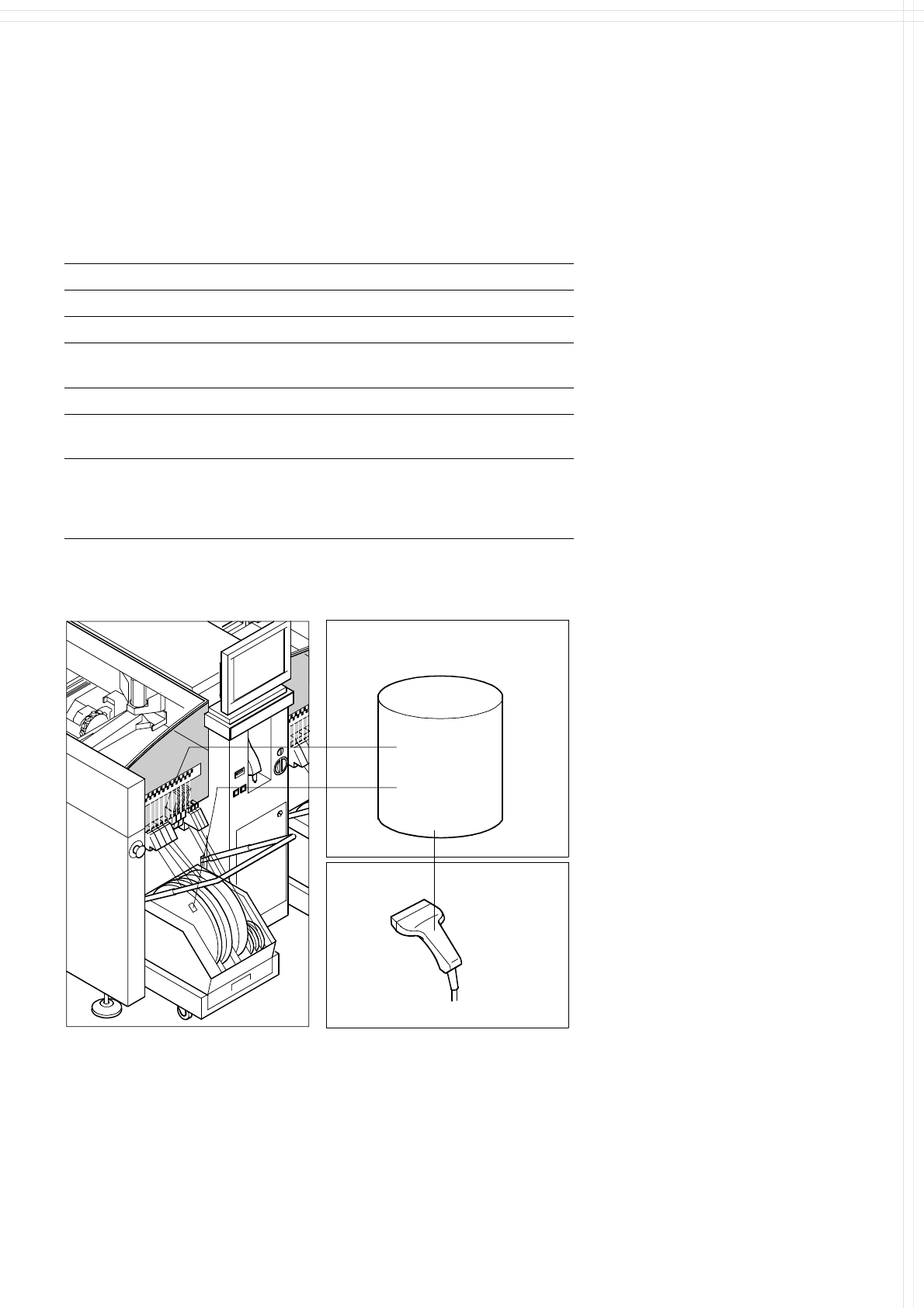
Component Bar Code Scanner for Set-Up and Refill Check
(Option)
Technical Data
Connection Station computer
Data entry Bar code scanner or keyboard
Number of characters Max. 40
Restrictions Bar codes beginning with number 1, 2,
3 or 4 and with less than 5 characters
Number of bar codes Max. 6 per component
Number of filters to blank out
data
Max. 1 per bar code
Preset types of codes Code 39 (standard or full ASCII),
Code 2 from 5 interleaved and normal,
Code 128, UPC/EAN/JAN codes
(more upon request)
Description
The component bar code scanner
enables a speedy, reliable set-up
and component replenishment
verification. To this end the bar
codes of the tracks (on the track
scale on the feeder table) and the
components allocated to them (bar
code labels on tapes, Bulk Cases,
etc.) are read in with a hand scan-
ner. An audible and optical signal
acknowledges a successful read-
ing operation. If a label is dam-
aged, the bar code can also be en-
tered at the keyboard.
The allocation of the components
to their respective track is de-
scribed in the set-up data. If the
data received from the bar code
scanner does not correspond with
the set-up data, an error message
is displayed.
Component
Control
Set-Up File
Track
Bar Code
If the set-up check is switched on,
it becomes a mandatory step in
the set-up process. If it is
switched off, the set-up check is
optional.
Component
Bar Code
Scanner
The scanner checks the corresponding track and the components.