00196642-01 - AI BE-Kamera 38 CPP_de_en.pdf - 第22页
6 Assembly Assembly Instruction SIPLACE X Series Edition 09/2009 22 Fig. 6.3.3 Component camera remov ed - ov er view X Make sure that all contact areas on the CPP head and the camera socket ( 3 ) are clean. X Carefully …
Assembly Instruction 6 Assembly
Edition 09/2009
21
In addition to the four screws (M4), the component camera is fixed to the intermediate distributor
with an M 2.5 x 4 screw. 6
6
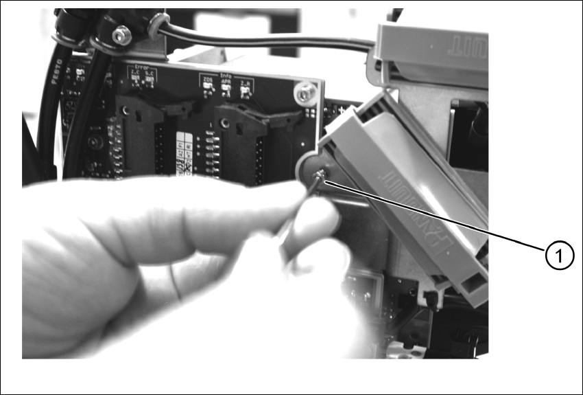
Fig. 6.3.2 Dismantling the placement head - safety screw
X Remove the safety screw (1).
X Carefully lift off the component camera.
6 Assembly Assembly Instruction SIPLACE X Series
Edition 09/2009
22
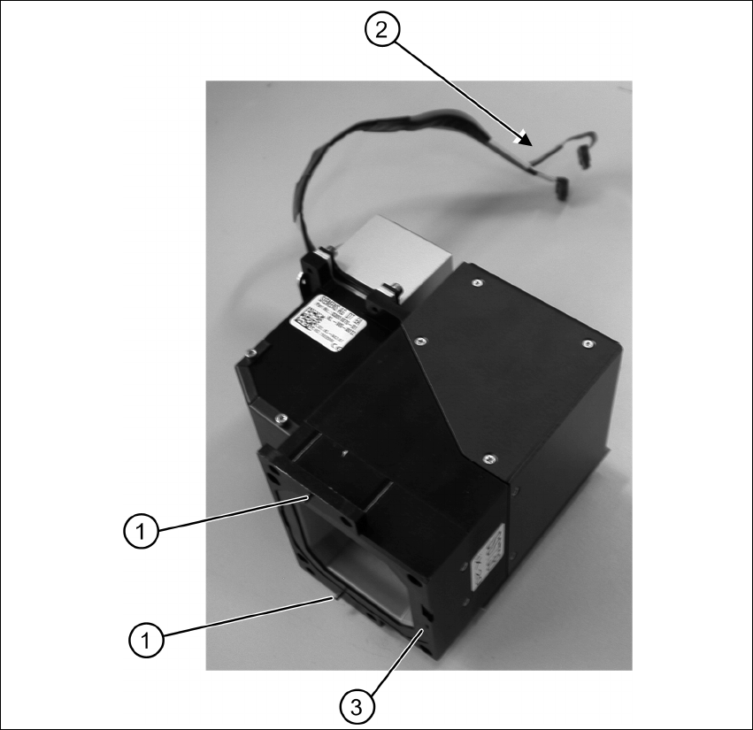
Fig. 6.3.3 Component camera removed - overview
X Make sure that all contact areas on the CPP head and the camera socket (3) are clean.
X Carefully place the new camera onto the CPP head with the two adjustment pins (1) into the
holes until the camera socket lies flush on the contact areas of the CPP head (3).
X Fix the camera with the four fastening screws.
X Fix the camera with the additional safety screw.
X Mount the placement head.

Assembly Instruction 6 Assembly
Edition 09/2009
23
Notes on Mounting the Placement Head
X Fix the four fastening screws with a torque of 2.7 N.
X Re-plug the connecting cable of the component camera (item 2 Fig. 6.3.3) into the vision
board.
X Mount the strain relief of the component camera cable.
X Re-connect the flat ribbon cables to the placement head (intermediate distributor).
X Re-establish the pneumatic connection.
6.4 Settings and Configuration
6.4.1 Calibrating the Component Camera and the Placement Head
In the station software execute the Fast Head Exchange function. The placement head and the
new built-in camera are being measured and calibrated. 6
– Calibration nozzles of type 2057 are required.
X In the station software confirm camera type 38 in the machine configuration.
X Under Service start the Fast Head Exchange function.
X Select the desired head and follow the instructions of the software.
6.4.2 Configuration in SIPLACE Pro
The new component camera must be entered into the setup. 6
X Open the desired setup in SIPLACE Pro.
X Select the Head tab for the corresponding location.
X Under Component Camera select the type "RV Camera (38) 20x20".
6
6
6
NOTE:
Observe the mounting notes in the Service Manual of the relevant machine.