nozzle.pdf - 第4页
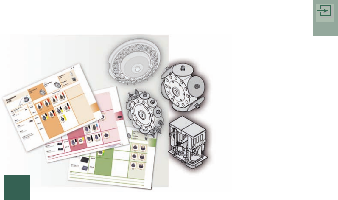
1 – 4 Y X Y X Y X I n trod u c ti on The primar y aim of this job guide is to make it easier for commissioning engineers and user s of SIPL ACE machines to sele ct noz zles. Y ou look for the compone nt to be placed (or …
General Information on Components
and Standard Nozzles
Introduction
Introduction
1 – 4
Y
X
Y
X
Y
X
Introduction
The primary aim of this job guide is to make it easier for
commissioning engineers and users of SIPLACE machines
to select nozzles.
You look for the component to be placed (or the package
form) in order to find out the appropriate nozzle to use.
The nozzles in this job guide are all standard nozzles. In the interests of preserving
clarity, the job guide does not contain special nozzles.
Structure of the Job Guide
This job guide is divided up into separate chapters that deal with different component groups.
To aid orientation, a sample component of the relevant component group appears on
the tab for each chapter. In the first (left-hand) column on each page you will find the
package form specifications of the different components. On the right you will find the
name of the associated package form (GF) file.
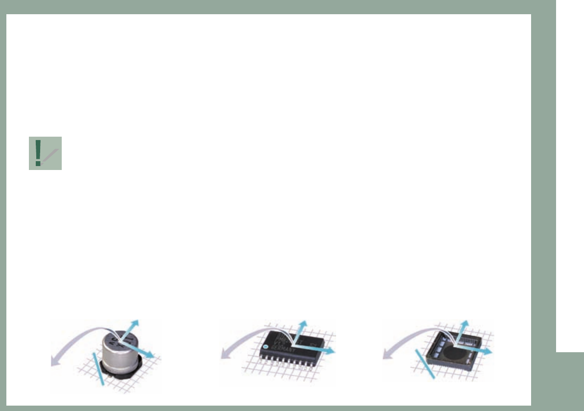
In addition, the 0° description of the sample component is shown on page 2 of each chapter.
Here are some examples:
0º
Description
0º
Description
0º
Description
1 – 5
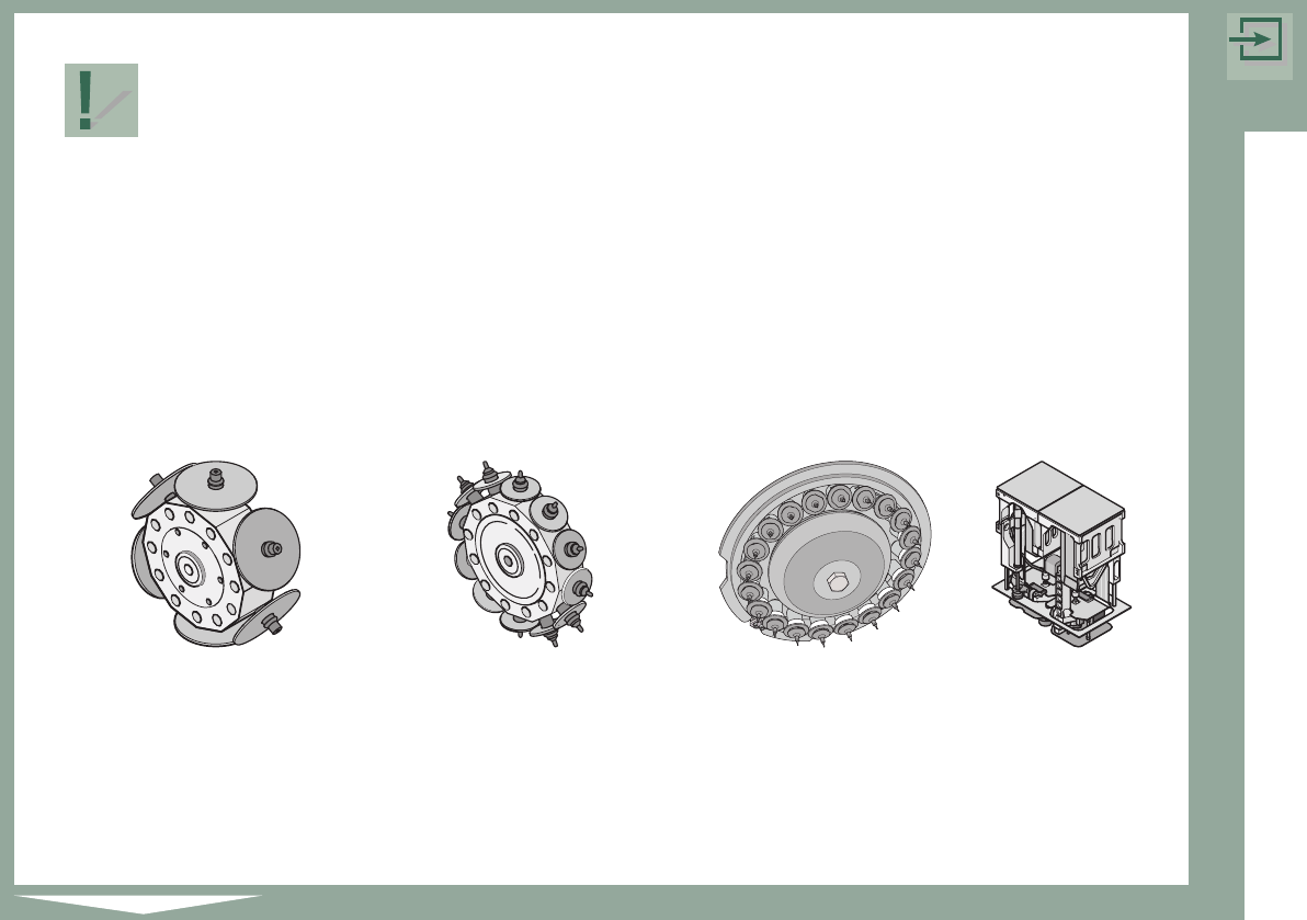
C&P-6
Collect & Place 6-Segment
C&P-12
Collect & Place 12-Segment
C&P-20
Collect & Place 20-Segment
Twinhead
The names of the package form (GF) files correspond to the
original file names in the package form (GF) editor of the line computer.
The nozzles that can be used for the package form(s) are shown in the four main columns
headed “Placement Head C&P-6, C&P-12, C6P-20, Twin”.
The following placement heads are used on SIPLACE machines of the X-Series:
Introduction