3_AVS-V2_MCT-UM-internal_EN_07-2019 - 第107页
ASM AVS - U SER M ANUAL P AGE 107 OF 182 Test Procedure Flow cha rt
ASM AVS - USER MANUAL
PAGE 106 OF 182
• If no USC is present, refer to the settings in the following table.
Parameter
Recommended Setting
Parameter
Recommended Setting
FRONT PRINT SPEED
25mms
-1
CHASE CLAMP PRESSURE
3 - 4 bar (nominal 3.5 bar)
REAR PRINT SPEED
25mms
-1
CLEAN REGIME
Double Dry Oscillate
PRINT FRONT LIMIT
40.0000 mm
CLEAN SPEED
Default
PRINT REAR LIMIT
40.0000 mm
STENCIL
FG Stainless 100µm
FRONT PRINT FORCE
39.24N (4.00 kg setting)
STENCIL FRAME
HTVG
FRONT PRINT FORCE
39.24N (4.00 kg setting)
PRINT MEDIA
Loctite 3616
SNUG FORCE
40N
SQA Width
250mm
BOARD CLAMP PRESSURE
3 bar
SQA Overhang
25mm
PRINT GAP
0.00mm
SQA Material
Stainless
SEPARATION SPEED
1.0000 mm/s
SQA Angle
60 degree
SEPARATION DISTANCE
3.0000 mm
Apply the glue
Insert the Stencil with the label (serial no., barcode) in the left front corner.
Ensure the glue has been removed from the fridge at least 8 hours before the test, and allowed to
warm up to ambient temperature.
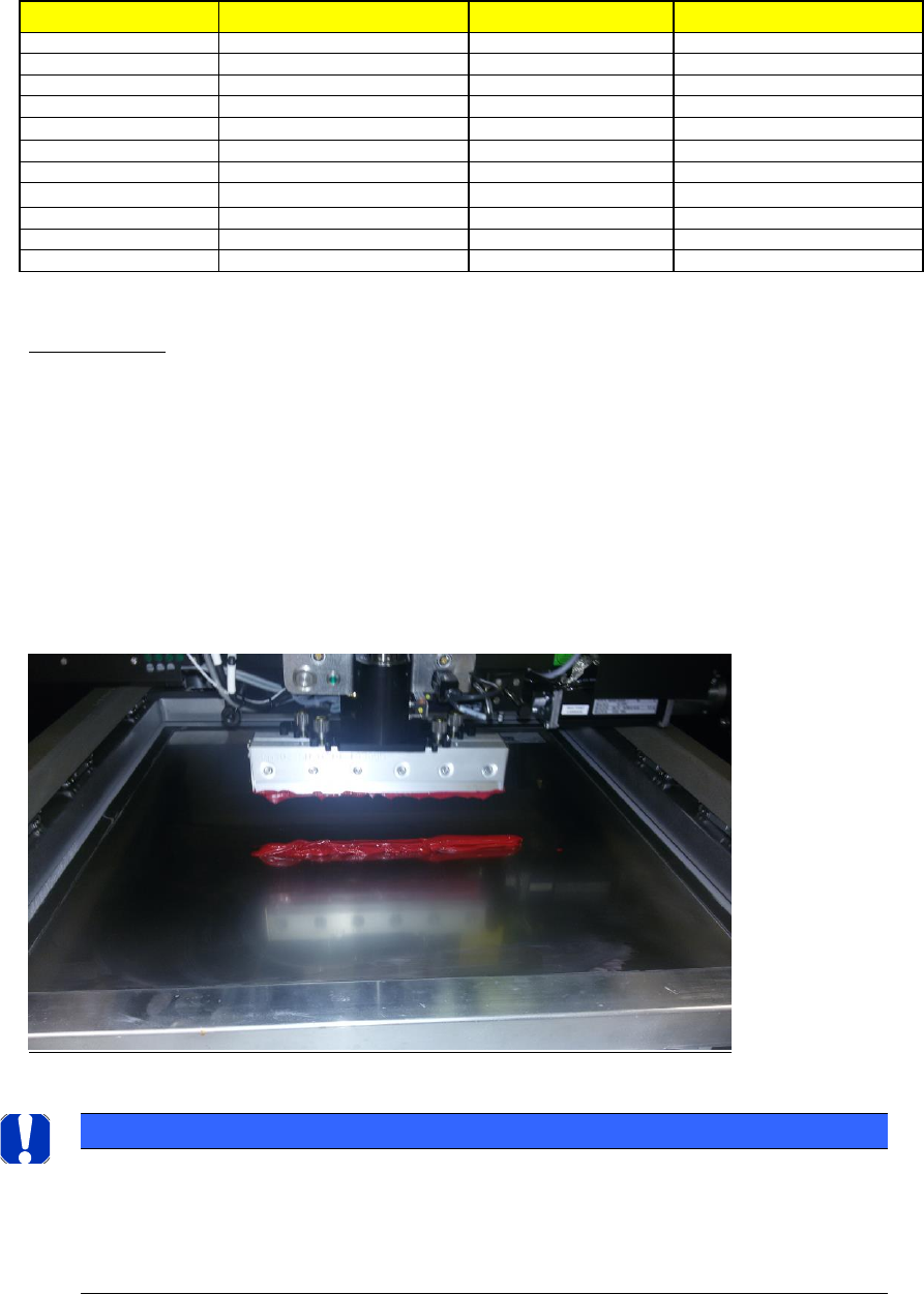
A bead of glue (print material) can now be added to the front of the image, this can be positioned
just in front of the first row of apertures and be around 15mm in diameter (see picture below).
Ensure the print direction is Front to Back.
NOTICE
Stencil and Glue recommendation
We recommend a Stencil with either 800µm circles or with 1mm Squares.
For the Paste material we recommend a Glue LOCTITE 3616 red, which can be purchased in a 400ml
cartridge, which can be clamped into a silicone-filled syringe from the hardware store.
ASM AVS - USER MANUAL
PAGE 107 OF 182
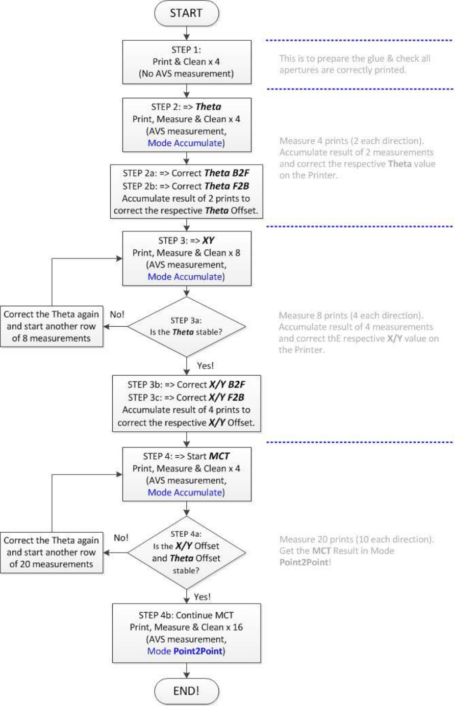
Test Procedure Flowchart

ASM AVS - USER MANUAL
PAGE 108 OF 182
5.2.25.3 Printer adjustment
Before completing the AVS test on a printing machine, the machine maintenance history
should be checked and any remedial work recommended is completed.
Step 1: Paste Preparation
First, 5 prints in each direction should be completed without AVS measurement. This is to
prepare the glue and stabilize the squeegee pressure, to ensure good consistent prints for the
test.
Step 2: Adjust (Theta)
Now make min. 4 prints, 2 in each direction, Front to Back (Reverse direction) and Back to
Front (Forward direction), obtain (Theta) rotational error correction, which are then applied
to the machine.
On the following steps during X/Y adjustment, check the theta to make sure it is stable.
Step 3: Adjust X/Y
Now make min. 4 prints, 2 in each direction, Front to Back (Reverse direction) and Back to
Front (Forward direction), obtain (Theta) rotational error correction, which are then applied
to the machine.
On the following steps during X/Y adjustment, check the theta to make sure it is stable.
Step 4: Perform MCT
Mark the first measurement that you would like to measure in the stable measurement se-
ries, e.g. by writing "Start MFU" into the comment field of the measurement.
From this measurement, you must perform at least 20 measurements (10 in each direction).
Parameters for printer adjustment in AVS Software
The main parameters what can be adjusted on a printer during a MCT are:
X-Offset: as a result of the AVS measurement
Y-Offset: as a result of the AVS measurement
Stencil rotation (Theta): as a result of the AVS measurement
Print speed: determined by the evaluation of the printing quality.
Print pressure: determined by the evaluation of the printing quality.
Separation distance: determined by the evaluation of the printing quality.
Separation speed: determined by the evaluation of the printing quality.
NOTICE
Use USC – Vac/Dry if possible.
Use Dry with OSC using cyclone cleaner system!