3_AVS-V2_MCT-UM-internal_EN_07-2019 - 第111页
ASM AVS - U SER M ANUAL P AGE 111 OF 182 5.2.25.7 Printer Project Analysis-Tab As alre ady m ent ione d i n the int rodu ctio n i n 5 .2.25 .1 , rev iew / a nalys is o f p rinte r me asu re- me nts c annot be don e i n t…
ASM AVS - USER MANUAL
PAGE 110 OF 182
5.2.25.6 Printer Project Recipe-Tab
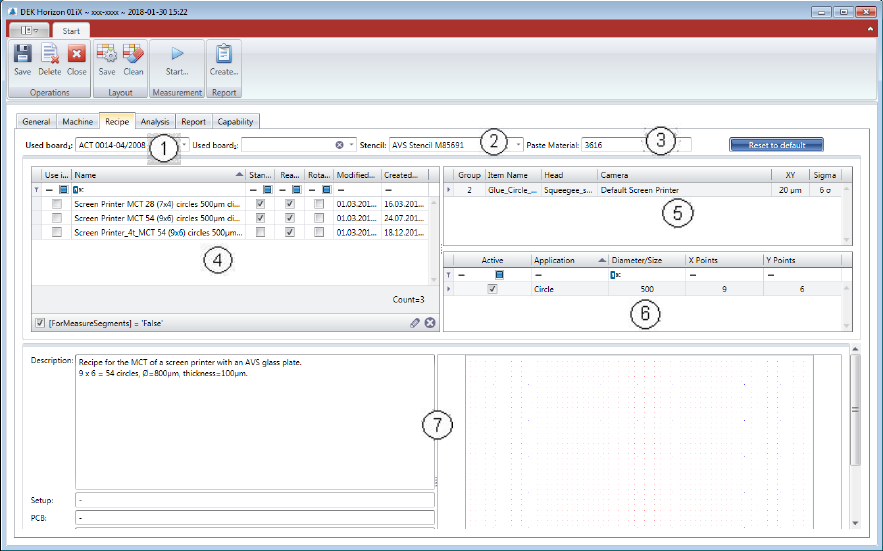
(1) Select measurement board:
Choose a board from the list. The board must be configured in the database and assigned to
the present AVS device. You can dedicate a second board to the project, in case that you like
to use a second board to accelerate the process.
(2) Stencil allocation:
Choose a stencil from the list. The stencil must be configured in the database and allocated
to the device.
(3) Paste allocation:
The paste or the glue which is used, must be entered in text format.
(4) The recipe list is empty at the beginning. Once you choose a Stencil from the list (2), the rec-
ipes which are connected to the stencil are being listed. Select one Recipe with the check-
box in the left side.
(5) In the Item configuration list, there is normally only one line, so there is not much to con-
figure. At this point you can change the specification for this project. And you can go back to
default spec. with the blue colored button above.
(6) In this table you find the information to the applications that are available on the stencil.
(7) Detailed information and layout of the selected recipe.
ASM AVS - USER MANUAL
PAGE 111 OF 182
5.2.25.7 Printer Project Analysis-Tab
As already mentioned in the introduction in 5.2.25.1, review / analysis of printer measure-
ments cannot be done in the same way as with a placement machine.
The single measurements, in the printer mode "Single", or several individual measurements in
the printer mode "Accumulate" are only used for setting the printer parameters, or for ad-
justing the offsets.
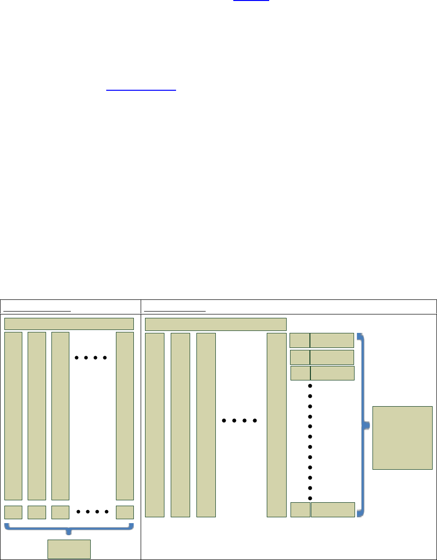
To evaluate the MCT, the printer mode "Point2Point" is required.
For details, see 5 Printer mode:
For example: A stencil (recipe) has 7x4 = 28 measurement points. So, 20 measurements for a
MCT, gives 560 measuring points.
To increase the safety on calculation, all 560 measuring points are used when calculating cm /
cmk values. But these are grouped first (1
st
point, 2
nd
point, ... to 28
th
point) and from each of
these groups, the standard deviation and average value are calculated. Subsequently, these
28 standard deviations are averaged to one standard deviation and also the 28 mean values
are summarized to one average mean value.
However, since this calculation cannot be represented graphically, there is a slight difference
between the statistical calculations and the graphical representation.
The graphs refer to a "Board2Board" view.
Board 2 Board:
Point 2 Point:
1
X-, Y-
.
.
.
.
.
.
.
.
.
.
.
.
.
.
.
.
28
times
Measurement
2
X-, Y-
.
.
.
.
.
.
.
.
.
.
.
.
.
.
.
.
28
times
3
X-, Y-
.
.
.
.
.
.
.
.
.
.
.
.
.
.
.
.
28
times
20
X-, Y-
.
.
.
.
.
.
.
.
.
.
.
.
.
.
.
.
28
times
Offset X
Offset Y
Offset X
Offset Y
Offset X
Offset Y
Offset X
Offset Y
Standard Deviation
and Mean Value
of 20 Board Offsets
1
X-, Y-
.
.
.
.
.
.
.
.
.
.
.
.
.
.
.
.
28
times
Measurement
2
X-, Y-
.
.
.
.
.
.
.
.
.
.
.
.
.
.
.
.
28
times
3
X-, Y-
.
.
.
.
.
.
.
.
.
.
.
.
.
.
.
.
28
times
20
X-, Y-
.
.
.
.
.
.
.
.
.
.
.
.
.
.
.
.
28
times
Standard Deviation
Mean Value
1. point
1 Standard Deviation
and 1 Mean Value,
as an average of
56 Standard Deviations
and 56 Mean Values
(28 * X and Y)
of 28 Point-Offsets
over all 20
measurements
Standard Deviation
Mean Value
2.point
Standard Deviation
Mean Value
3 point
Standard Deviation
Mean Value
28.point
ASM AVS - USER MANUAL
PAGE 112 OF 182
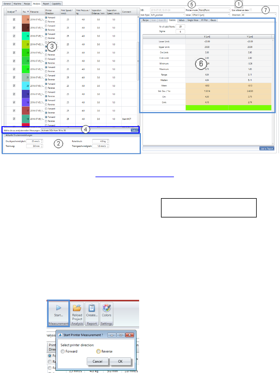
In the analysis tab are the most differences from a placement project to a printer project.
1. In case that there are stencil reference data available, you can activate the calculation of it,
with this checkbox. See 5.2.18.15 Base Data – Stencils
2. Before the measurement is started, the 4 parameters from the printer must be entered in the
fields below the measurement table.
- Print speed: in mm/sec. (25)
- Print pressure: in kg (4)
- Separation distance: in mm. (3)
- Separation speed: in mm/sec. (1)
Print speed and Print Pressure must be adjusted for both printing directions separately,
Forward and Reverse.
3. With each measurement the values from area 1 are being allocated to the measurement spe-
cific parameters.
With this procedure, a history regarding these parameters can be realized for the printer ad-
justment measures.
• Now, start the first measurement:
The printing direction is shown in the list, for each measurement with Radio buttons.
Recommendation with Loctite 3616 and
stencil with 800µm circles in brackets.
You will be directly asked for the printing di-
rection of the measurement.
For the first measurement there is no direction
preselected and you cannot continue, without
selection. On the start of each following meas-
urement, the direction will be changed auto-
matically and set per default. You just need do
check and confirm, or adjust.