3_AVS-V2_MCT-UM-internal_EN_07-2019 - 第147页
ASM AVS - U SER M ANUAL P AGE 147 OF 182 5.3.5.3.4 Mo ve components, cha nge grid • C hoose de sire d Ite m . • M ark t he compo nent s, you want t o chang e by draw ing a re cta ngle aro und th e com po nent wit h t he …
ASM AVS - USER MANUAL
PAGE 146 OF 182
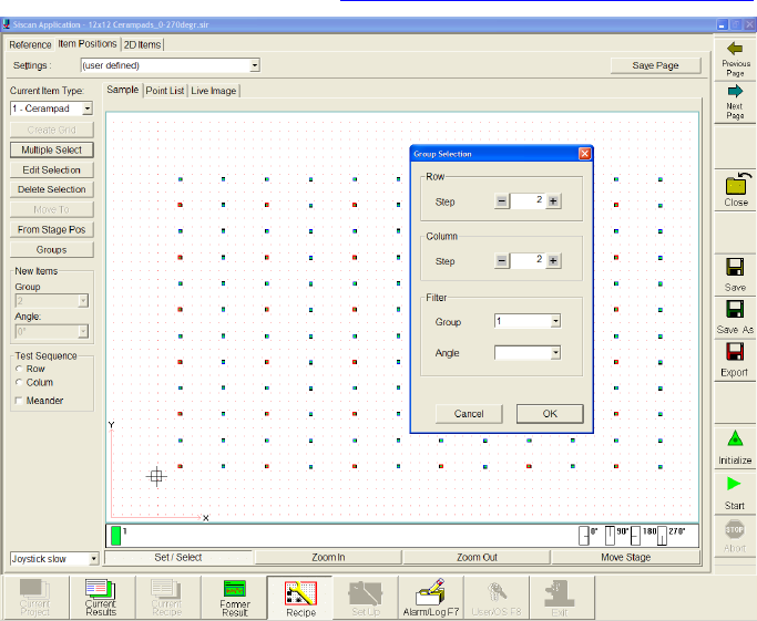
5.3.5.3.3 Multiple Select
• Mark the component, by drawing a rectangle around the component with the right mouse
button.
• Choose function »Multiple Select«.
• A window »Group Selection« will open. Here you can set the grid (Row/Colum) of which
component you want to mark within your filter settings.
• Later you can change some settings of the marked components with the
function »Edit Selection«. See 4.3.5.3.4 Move components, change grid
In this case every second component in Y- and X-direction is marked.
ASM AVS - USER MANUAL
PAGE 147 OF 182
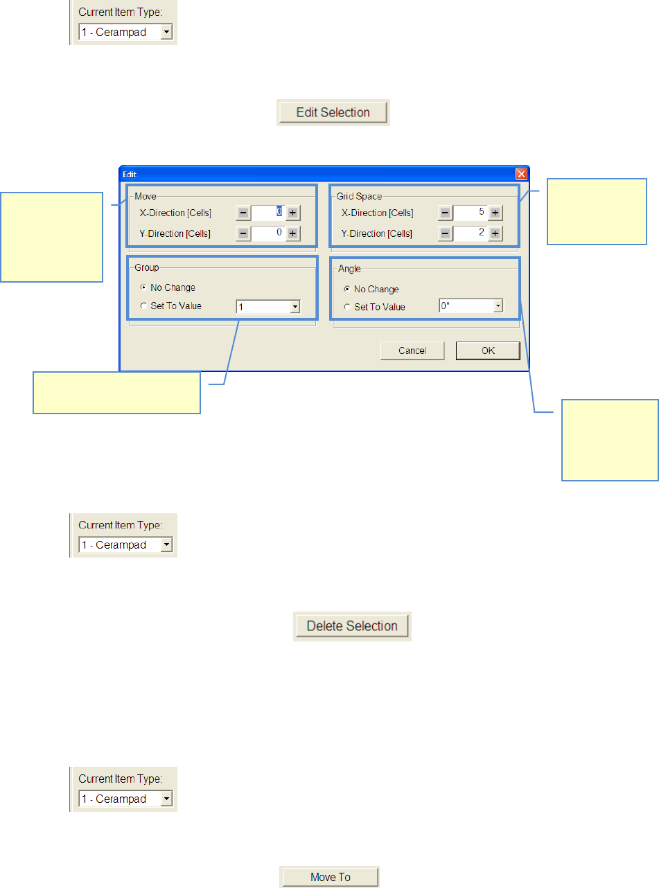
5.3.5.3.4 Move components, change grid
• Choose desired Item.
• Mark the components, you want to change by drawing a rectangle around the component
with the right mouse button
• Select function »Edit Selection«
• Modify your settings according to your desired measuring plan.
5.3.5.3.5 Delete components from recipe
• Choose component type which you want to delete.
• Mark the components, you want to delete by drawing a rectangle around the component
with the right mouse button.
• Select function »Delete Selection« , or push »Delete« button on key-
board.
5.3.5.3.6 Approach component with camera
• Select component you want to approach.
• Mark the components, you want to delete by drawing a rectangle around the component
with the right mouse button.
• Click on the button »Move To«. .
Distance of
components to
each other can
be changed
Marked compo-
nents can be
moved in X-
(horizontal) and
Y-direction
(vertical)
The angle of
marked com-
ponents can be
changed to
another value.
The group of marked compo-
nents can be changed.
ASM AVS - USER MANUAL
PAGE 148 OF 182
5.3.5.3.7 »From Stage Pos«
With the function »From Stage Pos«, you are able to place components at the location of the
camera.
• Move the camera with the function »Move Stage« to a position on your glass board.
• After the camera has reached the position, you can push the button »From Stage Pos«.
• Now you get a new component in the center of the closest 4 dots group.
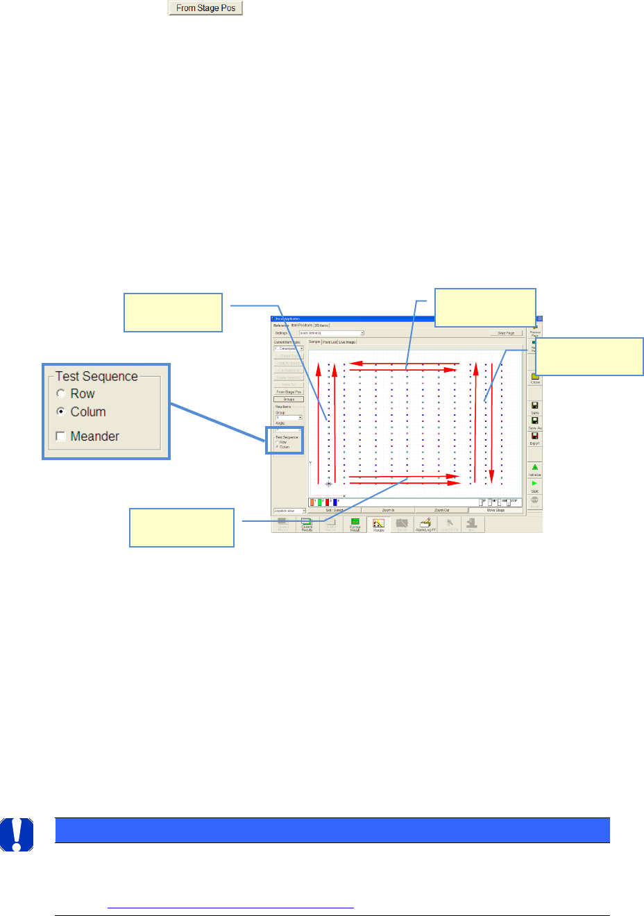
5.3.5.3.8 Adjustment of measurement sequence
• You have created a recipe (measuring plan).
• Now, you can adjust the measurement sequence.
• »Row« means: Measurement starts from the lower left side (component nr. 1). The cam-
era will be moved row by row and starts always to measure from the left side
• »Column« means: Measurement starts from the lower left side (component nr. 1). The
camera will be moved Colum by Colum and starts always to measure from the lower side
• The camera returns to the next component again, seen in a horizontal direction and moves
along the column in the same direction again
• »Meander« means: If a row or a column was measured, the camera does not return to the
next component again next to the 1st component but it moves along the next row or col-
umn in an opposite direction
NOTICE
The order of the measuring is mirrored again to 100% in the graphic "single value diagram". Therefore pay
attention at the interpretation of the graphic to the measuring order!
See also 6.4.2 Notes on evaluating the Single Value chart:
Test Sequence:
Row+Meander
Test Sequence:
Colum+Meander
Test Sequence:
Colum
Test Sequence:
Row