3_AVS-V2_MCT-UM-internal_EN_07-2019 - 第18页
ASM AVS - U SER M ANUAL P AGE 18 OF 182 2.1.3.5.2 03059289-01 „ Tray holder S “ Thi s t ray holde r c an be used in all Sip lace ma chin es wit h S-t able s. The de sign o f t he tray carri er f oll ows the c onc ept o f…
ASM AVS - USER MANUAL
PAGE 17 OF 182
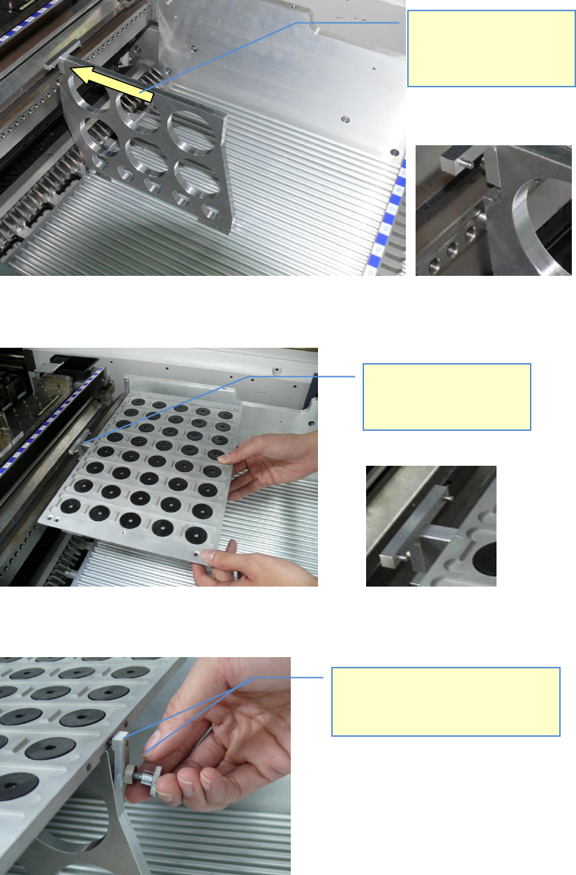
Once the tray carrier is placed on the table, the tray can be placed.
For security, the Tray can be fixed on the backside with the part:
03067242-01 Protection block
Move the tray holder forward
to the front end of the table,
until the pin on the front side of
the carrier moves into the X-
FCU hole.
Set the tray onto the carrier
(centered) and move it onto the
two pins of the carriers T-part.
To fix the tray with the 03067242-01 „safety
block“, you can use the 03031104-01 „DIN
464 M4 x 16 units (knurled-head bolts)“,
which you get from the tray’s cover.
ASM AVS - USER MANUAL
PAGE 18 OF 182
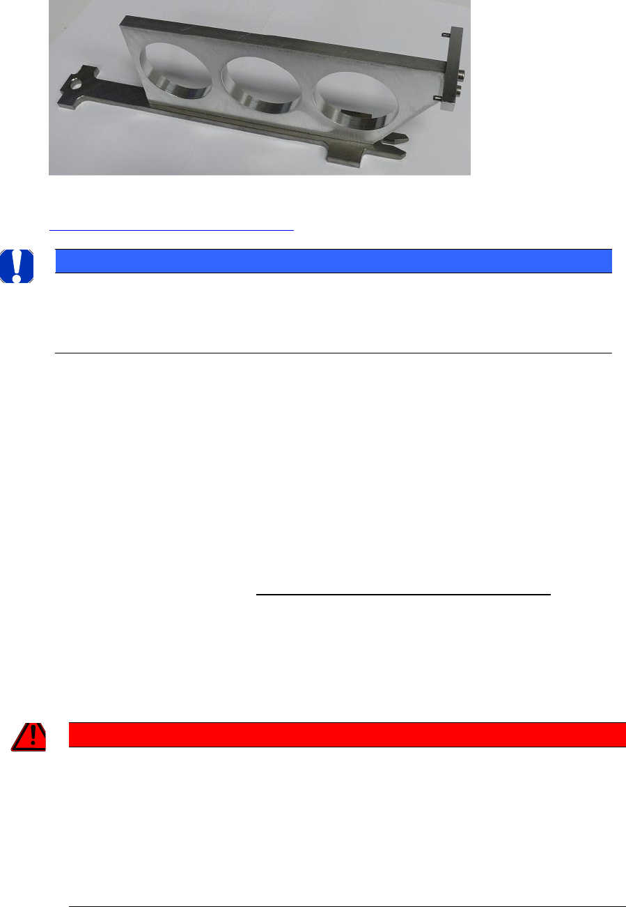
2.1.3.5.2 03059289-01 „Tray holder S“
This tray holder can be used in all Siplace machines with S-tables.
The design of the tray carrier follows the concept of an S-Feeder.
The tray has to be mounted in the same way, as described for the X-tray carrier above
2.1.3.5.1 03059291-01 „Tray holder X“.
NOTICE
2TReaching the Tray positions
Using it on X-, D-and HF- machines, it has to be set up on Track 37. This is necessary because of the reduced
travel range of X-, D-and HF- machines. For all other machines it can be set up as described in Siplace Pro.
2.1.3.6 Tray in the PCB conveyor
The trays for the glass components are, from the external dimensions, constructed in that
way, that the can moved into a conveyor like a glass board.
This has two advantages:
• All components can be placed without interruption. In case of a setup on a table, only a
few rows can be picked up, due to bad accessibility.
• The setup from the customer must not be changed.
A safe process is only valid from Station Software 708.xx and SIPLACE Pro 12.x upwards!
From SIPLACE Pro 12.x the following is possible:
1. Selection of a tray carrier „Conveyor Tray“ for the setup.
2. Fiducial recognition on trays (also from SIPLACE Pro 11.x on).
GEFAHR / DANGER
2T!!! Danger of Head Crash when using on older software versions !!!
Supporting the components on the conveyor track, board descriptions must be set to synchronous mode
and be equipped with Inkspots.
The detection of the ink spots ensures that components are only picked up when the plates are actually
present (=> no optimistic pre-pick).
On dual conveyors the synchronous description assures, that the plate (actually the tray) has arrived in the
assembly area before beginning the placement process (ink spot recognition).
ASM AVS - USER MANUAL
PAGE 19 OF 182
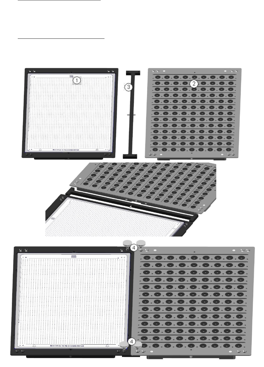
2.1.3.6.1 Hardware
Feeding in dual conveyor mode
In machines with dual conveyor, the glass plate can be fed in one lane and the tray in the other
lane.
Feeding in single conveyor mode
Connect the tray (1) with the glass plate (2), using the supplied adapter (3) and fasten the con-
nection with the 4 knurled screws (4) „DIN 464 M4 x 12-St (knurled screw)“ [03031103-01].