3_AVS-V2_MCT-UM-internal_EN_07-2019 - 第24页
ASM AVS - U SER M ANUAL P AGE 24 OF 182 2.1.3.6.3 Restri ctions • T ray in C onvey or f or ACT for X -t ables only The Option Tray in Conveyor is only possible f o r machi nes with X-tables. The option cannot be set up f…
ASM AVS - USER MANUAL
PAGE 23 OF 182
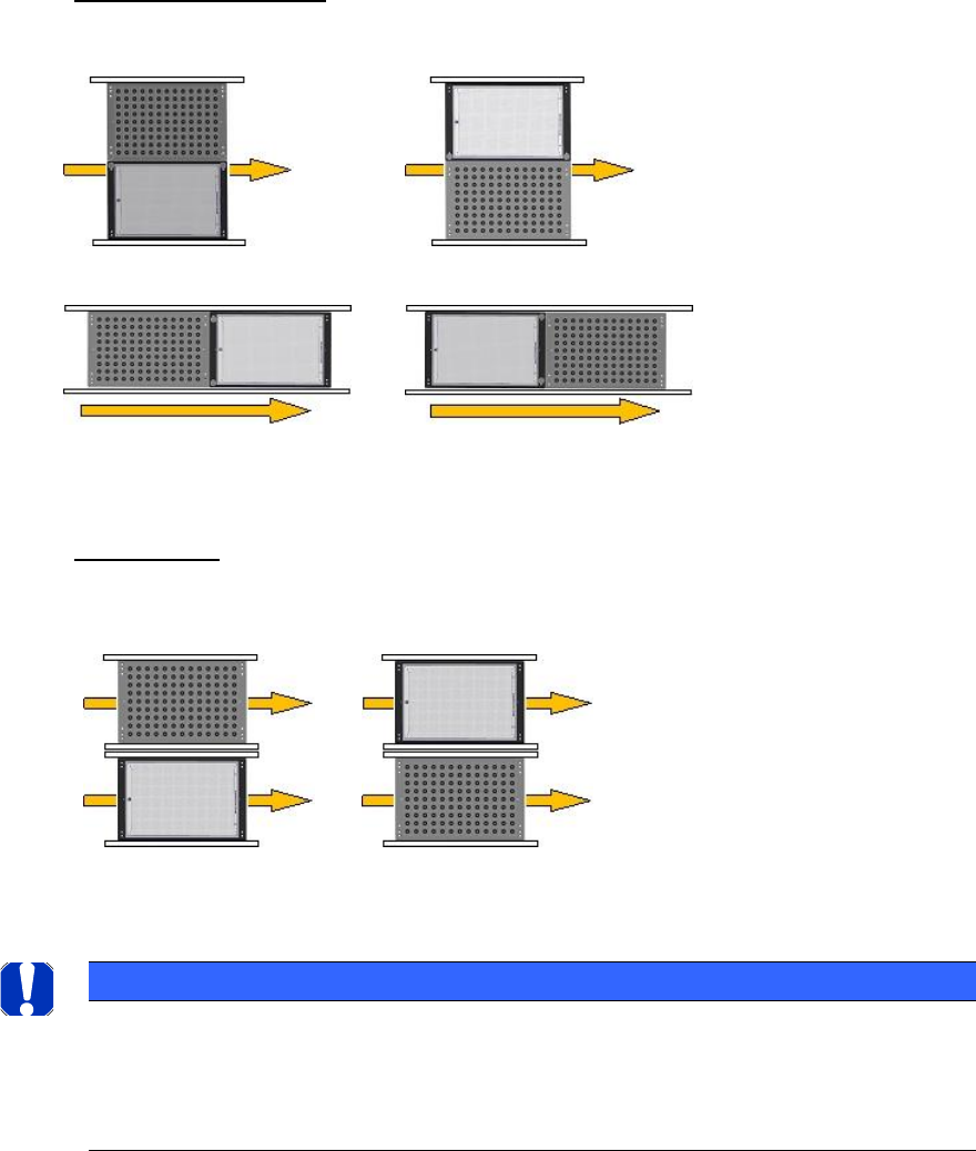
Position on the conveyor
This parameter is required for the single conveyor mode.
Conveyor lane
This parameter is required for the dual conveyor mode.
Left lane (2)
Right lane (1)
Tot he left of the board
To the right oft he board
Behind the board
In front of the board
NOTICE
2TPick up positions
You do not have to enter any offset values.
By using the Conveyor Carrier X tray carrier, the pickup position is automatically specified by the board
reference corner in the machine.
ASM AVS - USER MANUAL
PAGE 24 OF 182
2.1.3.6.3 Restrictions
• Tray in Conveyor for ACT for X-tables only
The Option Tray in Conveyor is only possible for machines with X-tables.
The option cannot be set up for S-tables.
Reason:
– Station Software 60x is not equipped with the new functions.
– Station Software 70x cannot operate S-tables.
Possible: X-series S, SX-series, DX-series, X-series with X-tables.
Not possible: D-series, X-series with S-tables.
• Number and position of the components in the tray
Feeding the tray In front of Board or Behind Board (see the position on conveyor parame-
ters), is only possible with SX1/2 and DX1/2 machines.
• Make sure that the components are correctly inserted into the tray.
• Adapt the tray description, because pickup will only be possible from a few rows.
Additionally, a "short adapter" [03055995S01] is required to connect the glass plate with the
tray on the short side.
ASM AVS - USER MANUAL
PAGE 25 OF 182
3 Setup and start-up:
3.1 Setup and cabling
The »ASM AVS Service Tool complete« (part no.: 0003062962-01) is transported to the custom-
er's premises in 3 large, air freight boxes. These boxes can be connected to one another for
trans-port or may be separate.
The bottommost box also contains 4 rollers and a reinforced base plate.
This box contains the lower part of the ASM AVS, which includes an industry PC.
This part usually remains on the base plate supplied in the box.
As a result, it is an easy matter to transport the SISPLACE AVS from one line to another at the
customer's premises.
NOTICE
The ASM AVS should always be placed as close as possible to the line computer or SIPLACE PRO computer
that is controlling the line.
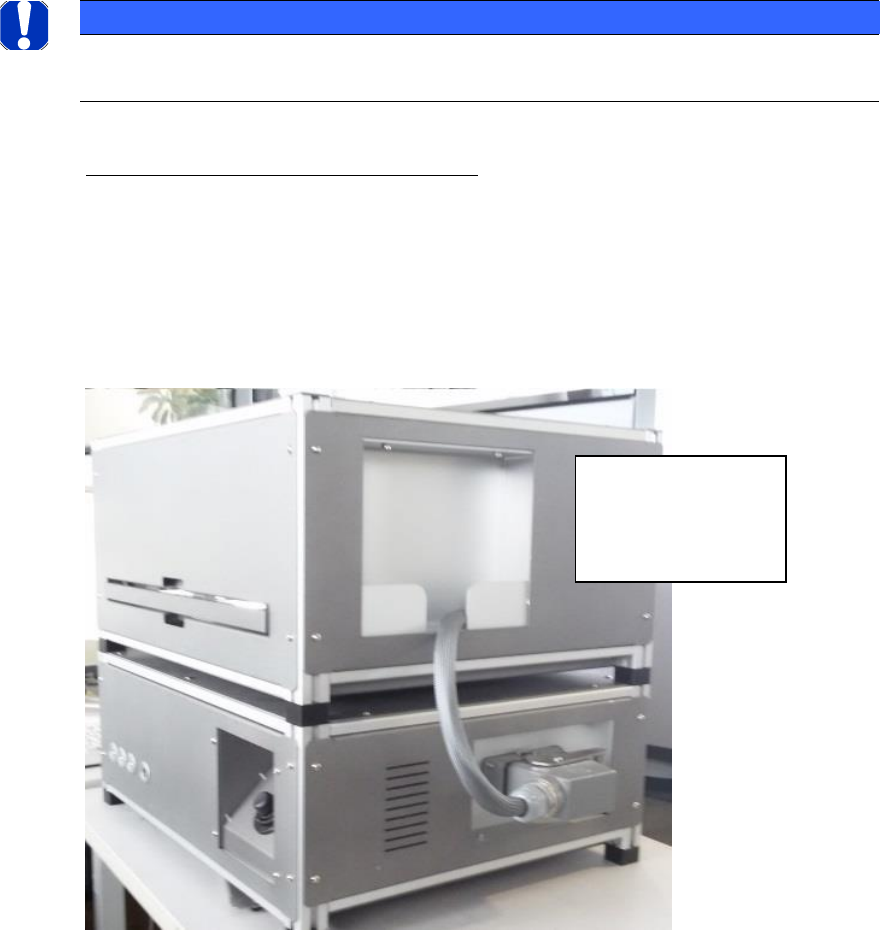
Connection cable (upper part/lower part):
Subsequently, the upper part must be connected to the lower part via the cable.
The cable is pull protected mounted on the upper part and the solid plug is housed in a tray in
the housing of the upper part.
The plug must be plugged and locked to the base.
When removing, the
plug must be parked
in the shell of the
upper part.