3_AVS-V2_MCT-UM-internal_EN_07-2019 - 第25页
ASM AVS - U SER M ANUAL P AGE 25 OF 182 3 Setu p and st art - up: 3.1 Set up and cab lin g The »A SM A VS S ervi ce To ol com plet e« (pa rt no .: 0003 0629 62-0 1) is t ran sport ed to t he c ustom - er' s pr emis …
ASM AVS - USER MANUAL
PAGE 24 OF 182
2.1.3.6.3 Restrictions
• Tray in Conveyor for ACT for X-tables only
The Option Tray in Conveyor is only possible for machines with X-tables.
The option cannot be set up for S-tables.
Reason:
– Station Software 60x is not equipped with the new functions.
– Station Software 70x cannot operate S-tables.
Possible: X-series S, SX-series, DX-series, X-series with X-tables.
Not possible: D-series, X-series with S-tables.
• Number and position of the components in the tray
Feeding the tray In front of Board or Behind Board (see the position on conveyor parame-
ters), is only possible with SX1/2 and DX1/2 machines.
• Make sure that the components are correctly inserted into the tray.
• Adapt the tray description, because pickup will only be possible from a few rows.
Additionally, a "short adapter" [03055995S01] is required to connect the glass plate with the
tray on the short side.
ASM AVS - USER MANUAL
PAGE 25 OF 182
3 Setup and start-up:
3.1 Setup and cabling
The »ASM AVS Service Tool complete« (part no.: 0003062962-01) is transported to the custom-
er's premises in 3 large, air freight boxes. These boxes can be connected to one another for
trans-port or may be separate.
The bottommost box also contains 4 rollers and a reinforced base plate.
This box contains the lower part of the ASM AVS, which includes an industry PC.
This part usually remains on the base plate supplied in the box.
As a result, it is an easy matter to transport the SISPLACE AVS from one line to another at the
customer's premises.
NOTICE
The ASM AVS should always be placed as close as possible to the line computer or SIPLACE PRO computer
that is controlling the line.
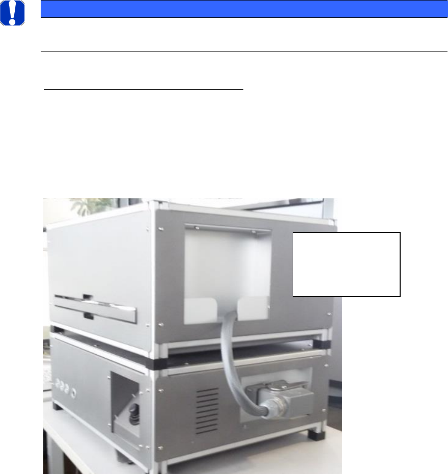
Connection cable (upper part/lower part):
Subsequently, the upper part must be connected to the lower part via the cable.
The cable is pull protected mounted on the upper part and the solid plug is housed in a tray in
the housing of the upper part.
The plug must be plugged and locked to the base.
When removing, the
plug must be parked
in the shell of the
upper part.

ASM AVS - USER MANUAL
PAGE 26 OF 182
Power connection cable (power supply):
The ASM AVS is powered by means of a mains cable (for insulated devices). The power switch is
located directly beside.
LAN - Connections
ASM AVS possesses a total of 2 Ethernet LAN connections.
REMOTE_LAN is placed on the front side of the lower part and it is directly connected to the
computer.
This connection must be used for the Remote Support connection. It possesses a fixed TCP/IP
address (169.254.100.xxx) via which the computer is controlled.
At the back is the LAN connection point for SIPLACE_LAN.
Here, the network cable that connects the placement line to the customer's SIPLACE Pro or line
computer can be plugged in.
Older devices have 3 LAN ports on the back.
These are connected to a LAN switch inside the AVS device, so that all 3 connections are equiva-
lent. For older SIPLACE machines, the station computer and the machine controller (MC) can be
connected directly to the AVS and used as a machine hub.
Please also note the information on the procedure for controlling the placement line in section
5 Communication Service Notebook ASM AVS SIPLACE