3_AVS-V2_MCT-UM-internal_EN_07-2019 - 第8页
ASM AVS - U SER M ANUAL P AGE 8 OF 182 2. 1.3 ASM A VS acc essor ie s 2.1.3.1 Measurement plates The me asurem ent pl ate (Cal ibra tio n boa rd s ing le ki t 030 56448 - 01) is a gla ss bo ar d (30 0 x 200 x 4 mm ) o n …
ASM AVS - USER MANUAL
PAGE 7 OF 182
2 Details to AVS Device and accessories
2.1 ASM AVS
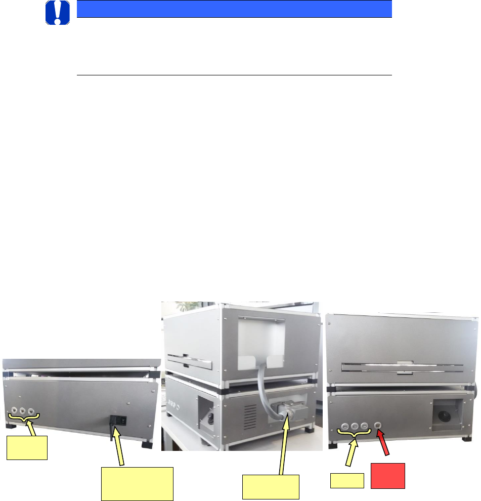
The ASM AVS device consists of 2 modules:
• Part 1: Computer with outbound interfaces.
• Part 2: Board seating, axis system with camera, background lighting.
2.1.1 ASM AVS lower part (03061515-02), part 1:
The lower part of the device contains a Siematic Box PC 827C.
This PC has the following tasks:
• Application of the ASM AVS software.
• Axis control (stepping motors)
• Measurement with digital SIPLACE Vision
• Control of the placement line (SIPLACE Pro)
2.1.2 ASM AVS upper part (03061131-01)
The upper part contains the axis system and the illumination unit for the background lighting.
The axis system, which is controlled with stepping motors, contains a standard PCB camera
from the SIPLACE X series.
The glass board with the placed components is fed into the system via a drawer.
NOTICE
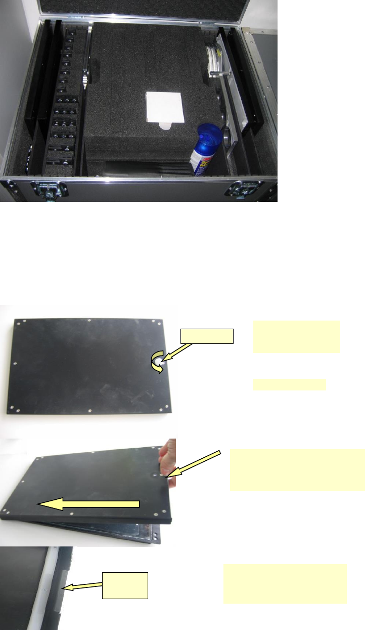
AVS Checklist
Details and part numbers to all parts, that comes with a MCT Tool-Set, can be
found in the document „1_AVS-V2_Checkist_Edition_mm-jjj.pdf“
Remote
LAN
Network connec-
tion (230V~ insulat-
ed devices), switch-
es
SIPLACE
LAN
USB 2.0
Connections
to upper part
ASM AVS - USER MANUAL
PAGE 8 OF 182
2.1.3 ASM AVS accessories
2.1.3.1 Measurement plates
The measurement plate (Calibration board single kit 03056448-01) is a glass board (300 x 200 x
4 mm) on which a chrome structure has been applied on one side.
This glass board is glued inside an aluminum frame using silicon.
Knurled bolt
The cover is fixed to the
board frame using a
knurled bolt.
• Unscrew bolt.
Mounting
braket
On the other side (opposite the
bolt fixing), the cover is held in
place only by the mounting brack-
et.
• Raise the cover slightly on this
side.
• Next, push cover to left while
holding the board in the frame.
ASM AVS - USER MANUAL
PAGE 9 OF 182
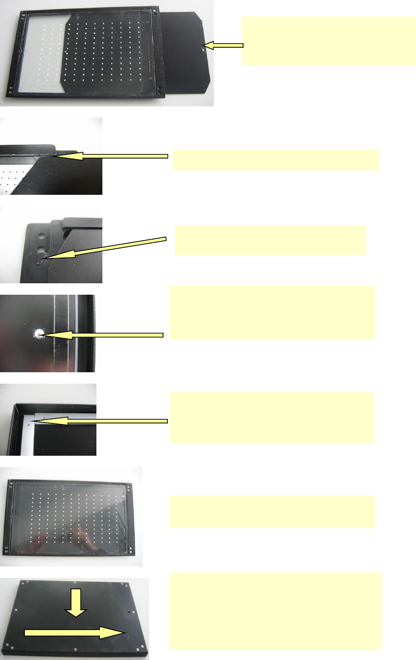
• On the underside, the glass board is protected
by a thin metal plate.
It is known as the "reflective" plate since it can
be used as a background for reflective meas-
urements.
• The reflective plate slides lengthways into a groove
below the glass plate.
• There is a stop on one of the side edges of the
frame to prevent the reflective plate passing right
through.
• If the reflective plate is pressed against the stop then
the 4mm hole in the reflective plate coincides exactly
with the threaded hole for the knurled-head bolt. As a
result, when the knurled bolt is screwed in, it stops the
reflective plate moving.
On the one hand, the plastic strips on the inside of the
cover help seal the top of the glass board against dust.
On the other, they provide a safety margin to prevent the
cover from touching the spray adhesive on the glass board.
• To pack the board again, place the glass board on a flat
surface (table) after introducing the reflective plate.
• Next place the cover straight over the glass board and
then push it from left to right in order to move the mount-
ing bracket (see above) under the frame.
• You can now screw in the knurled-head bolt.
• However, do not screw it in fully. Instead after about half
a turn, lift the complete plate and press the reflective
plate at the bottom against the stop and then tighten the
knurled-head bolt.