Service Manual SIPLACE SmartFeeder.pdf - 第100页
7 Repairs to SmartFeeder 8 mm X / Xi 7.2 Rear Sliding Guide 100 Service Manual SIPLACE SmartFeeder 4 - 8 mm X / Xi SIPLACE SmartFeeder 2 x 8 mm X / Xi 11/2020 7.2.1 Removing the Sliding Guide ► Turn the feeder module so …
7 Repairs to SmartFeeder 8 mm X / Xi
7.2 Rear Sliding Guide
Service Manual SIPLACE SmartFeeder 4 - 8 mm X / Xi SIPLACE SmartFeeder 2 x 8 mm X / Xi 11/2020 99
7.2 Rear Sliding Guide
Required spare part
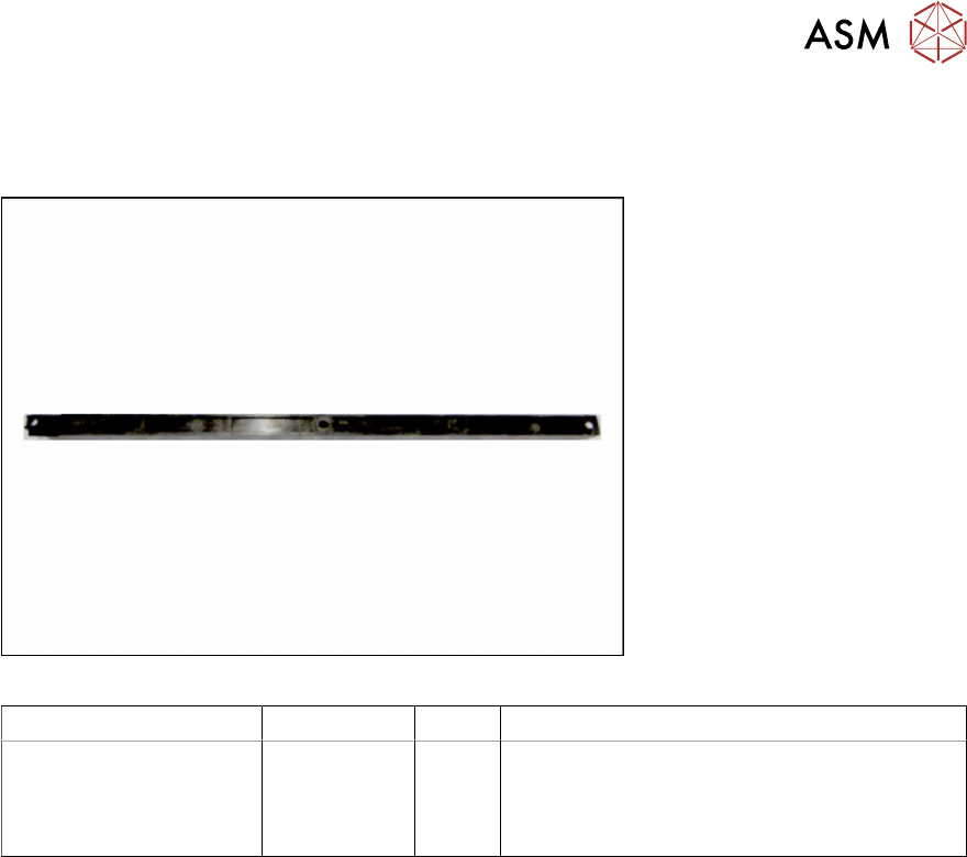
Fig.29: Sliding guide, back
Feeder module Item no. Type Designation
SmartFeeder 8mmX
SmartFeeder 8mmXi
03003994-xx
03010209-xx
03158711-xx
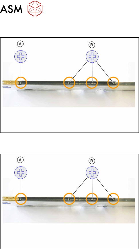
A
B
Sliding guide / back L200
ISO 7045 - M2.5 x 6-A2-50-H (1x)
Fillister head self-tapping screw DIN7981
2.9x9.5 (3x)
Tools required
●
TORX screwdriver 0.6Nm, size T8
7 Repairs to SmartFeeder 8 mm X / Xi
7.2 Rear Sliding Guide
100 Service Manual SIPLACE SmartFeeder 4 - 8 mm X / Xi SIPLACE SmartFeeder 2 x 8 mm X / Xi 11/2020
7.2.1 Removing the Sliding Guide
► Turn the feeder module so that its underside is at
the top.
► Remove the Phillips screw from the left side.
► Remove the three fillister head self-tapping
screws on the righthand side.
► Lift the gliding slide upwards and off.
7.2.2 Fitting the Sliding Guide
► Turn the feeder module so that its underside is at
the top.
► Fit the guiding slide to the underside of the feeder
module.
Observe the arrangement of the drilled holes in
the guiding slide.
► Push the guiding slide to the left (front) towards
the front guiding slide, as far as the stop.
► Now lower the two snap tabs of the guiding slide
into the openings provided on the underside of
the feeder module.
► Fasten the sliding guide on the left side to the
feeder module, using the Phillips screw (ISO
7045 - M2.5 x 6-A2-50-H) tightened to 0.6N.
► Fasten the sliding bearing on the righthand side
with the three fillister head self-tapping screws
(DIN7981 2.9x9.5), using 0.6Nm, to the feeder
module.
7 Repairs to SmartFeeder 8 mm X / Xi
7.3 Side Covers
Service Manual SIPLACE SmartFeeder 4 - 8 mm X / Xi SIPLACE SmartFeeder 2 x 8 mm X / Xi 11/2020 101
7.3 Side Covers
NOTICE
Avoiding damaging the board
To avoid damaging the threaded bolts on the printed circuit board, only remove the side
cover if the other side cover has been fully fitted i.e. with all screws.
Spare part required
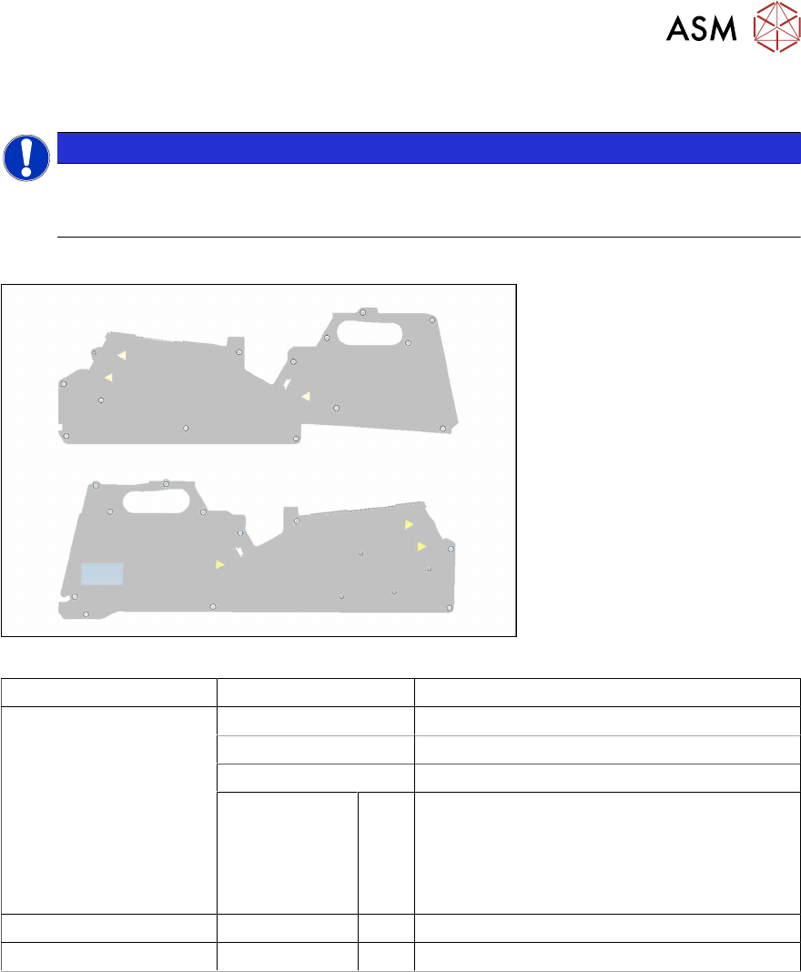
Fig.30: Side plate left assy. X8Smart (top), side plate right assy. X8Smart (bottom)
Feeder module Item no. Designation
SmartFeeder 8mmX
SmartFeeder 8mmXi
03100525Sxx Side plate left assy. X8Smart
03100526Sxx Side plate right assy. X8Smart
03225465-xx Foam sealing top 8 mm
03033796-xx
03023227-xx
03071821-xx
03044543-xx
A
C
D
E
Screws:
RF-SN75-2.5 x 6-9.8
ISO 7045 - M2.5 x 6-A2-50-H
SN 213307-H-M2.5 x 3-A2-70
RF-SN85-2.5 x 7.5-9.8
SmartFeeder 8mmX 03071822-xx B ISO 7046-2-M2.5 x 5-A2-70-H
SmartFeeder 8mmXi 03071822-xx B ISO 7046-2-M2.5 x 5-A2-70-H
Tools required
●
Phillips screwdriver 0.9Nm
●
TORX screwdriver 0.6Nm, size T8