Service Manual SIPLACE SmartFeeder.pdf - 第104页
7 Repairs to SmartFeeder 8 mm X / Xi 7.3 Side Covers 104 Service Manual SIPLACE SmartFeeder 4 - 8 mm X / Xi SIPLACE SmartFeeder 2 x 8 mm X / Xi 11/2020 7.3.4 Fitting the right side cover NOTICE! Observe the correct pos…
7 Repairs to SmartFeeder 8 mm X / Xi
7.3 Side Covers
Service Manual SIPLACE SmartFeeder 4 - 8 mm X / Xi SIPLACE SmartFeeder 2 x 8 mm X / Xi 11/2020 103
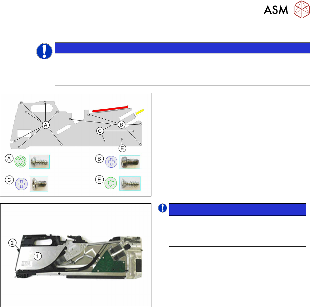
7.3.3 Removing the right side cover
NOTICE
Avoiding damaging the board
Before you remove the right side cover, make sure that the left side cover has been com-
pletely fixed in place with all screws. If not, the threaded bolts could be damaged on the
board.
► Carefully place the feeder module with the left
side down on a stable, level and clean surface.
► Loosen the screws marked A and E with a TORX
screwdriver.
► Loosen the screws marked B and C with a
Philips screwdriver.
The side cover is only inserted in the upper part of the
frame in the area marked red.
► Pull the side cover down and out.
NOTICE!
Please note that the foil container cover (1)
and flap (2) are only clipped or placed on! Re-
move these two parts before you change the
position of the feeder module.
.
A description of how to remove the cover and the foil
container flap can be found at 7.12.1
"Removing the
Flap" [}147].
7 Repairs to SmartFeeder 8 mm X / Xi
7.3 Side Covers
104 Service Manual SIPLACE SmartFeeder 4 - 8 mm X / Xi SIPLACE SmartFeeder 2 x 8 mm X / Xi 11/2020
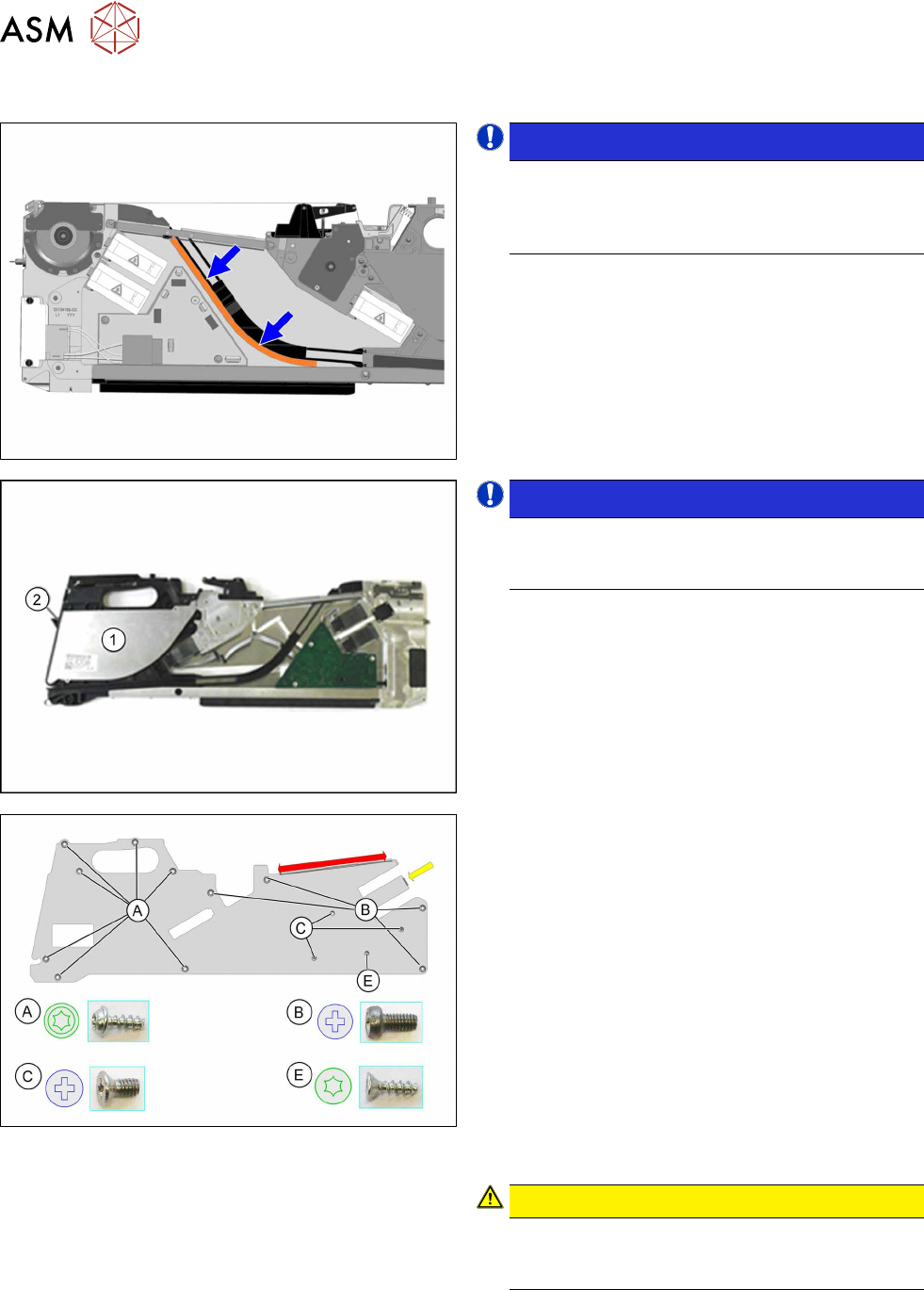
7.3.4 Fitting the right side cover
NOTICE!
Observe the correct position of the foam
seal. Make sure that the foam seal does not
get trapped in the empty tape duct or pro-
trude into it!
.
To check the correct position of the foam seal, remove
the left side cover, as shown (after fitting the right side
cover), and correct the position of the foam rubber if
necessary.
NOTICE!
Please make sure that the foil container
cover (1) and the foil container flap (2) are
correctly clipped on or placed on!
.
A description of how to fit the cover and the foil con-
tainer flap can be found in section 7.12.2
"Fitting the
Flap" [}148].
► Carefully place the feeder module with the left
side down on a stable, level and clean surface.
► Insert the side cover (in the area marked red), as
shown, under the rail, as far as the stop.
► Insert the side cover on the right side, in the area
marked yellow under the encoder.
► Fasten the screws as shown in the diagram. Be-
gin with the inner screws (C
) and work outwards
(B
+ A).
Fasten screw E
last
You need a Phillips screwdriver with 0.6 Nm for the
screws marked B
and C.
You need a TORX screwdriver with 0.6 Nm for the
screws marked A
.
Also use a TORX screwdriver for the screw marked E.
CAUTION!
Tighten screw E no more than hand-tight,
otherwise the screw fixtures inside the feeder
module could be damaged or broken.
.
7 Repairs to SmartFeeder 8 mm X / Xi
7.4 EDIF
Service Manual SIPLACE SmartFeeder 4 - 8 mm X / Xi SIPLACE SmartFeeder 2 x 8 mm X / Xi 11/2020 105
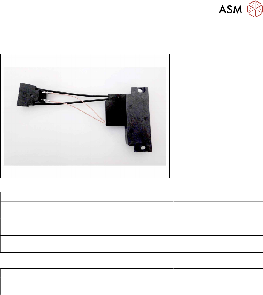
7.4 EDIF
Spare part required
Fig.31: EDIF secondary assembly
Feeder module Item no. Designation
SmartFeeder 8mmX (V1) 00141370-01
SmartFeeder 8mm X Splice (V1) 00141390-01
03101192Sxx EDIF secondary assembly X8S-
mart
SmartFeeder 8mmX (V2) 00141370-02
SmartFeeder 8mm X Splice (V2) 00141390-02
03127518- EDIF secondary assembly X8S-
mart
SmartFeeder 8mm Xi 00141480-xx
SmartFeeder 8mm Xi Splice 00141500-xx
03127518-xx EDIF secondary assembly X8S-
mart
Other spare parts:
Feeder module Item no. Designation
All feeder modules mentioned in the above
table
03012683-xx
03050957-xx
Pressure spring D-027
Collar screw D4x3.15 M3
Tools required
●
Flat-bladed screwdriver 0.9Nm
●
Phillips screwdriver 0.9Nm
●
TORX screwdriver 0.6Nm, size T8