Service Manual SIPLACE SmartFeeder.pdf - 第116页
7 Repairs to SmartFeeder 8 mm X / Xi 7.6 Splice sensor 116 Service Manual SIPLACE SmartFeeder 4 - 8 mm X / Xi SIPLACE SmartFeeder 2 x 8 mm X / Xi 11/2020 7.6.1 Replacing the Dummy with a Splice Sensor ► Place the feeder …

7 Repairs to SmartFeeder 8 mm X / Xi
7.6 Splice sensor
Service Manual SIPLACE SmartFeeder 4 - 8 mm X / Xi SIPLACE SmartFeeder 2 x 8 mm X / Xi 11/2020 115
7.6 Splice sensor
NOTICE
Removing retrofitted splice sensors
Each SmartFeeder 8mmX is prepared for using a splice sensor, although it is supplied
without the splice sensor. To re-establish this delivery state, you need to remove any retro-
fitted splice sensors before you send the feeder module back to the manufacturer for re-
pairs.
Spare part required
Splice sensor Dummy splice sensor
Sensor insertion tunnel X8Smart
Screw RF-SN65-2.5 x 12-9.8
Splice sensor filling piece assy.
Feeder module Item no. Designation
SmartFeeder 8mm X
SmartFeeder 8 mm Xi
03107028 -xx Splice sensor X8Smart assembly
03104558 -xx Dummy splice sensor X8Smart
03127503-xx Sensor insertion tunnel X8Smart
03033496-xx RF-SN65-2.5 x 12-9.8
03097801-xx Splice sensor filling piece assy.
Tools required
●
TORX screwdriver 0.6Nm, size T8
7 Repairs to SmartFeeder 8 mm X / Xi
7.6 Splice sensor
116 Service Manual SIPLACE SmartFeeder 4 - 8 mm X / Xi SIPLACE SmartFeeder 2 x 8 mm X / Xi 11/2020
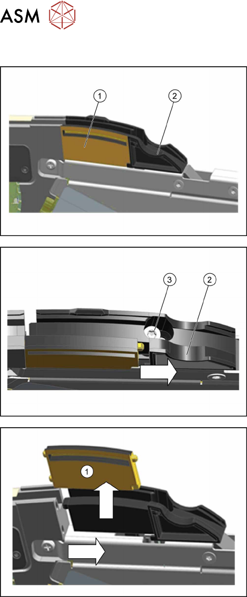
7.6.1 Replacing the Dummy with a Splice Sensor
► Place the feeder module in a stable, upright posi-
tion.
The dummy splice sensor(1) is located behind the
pickup window and is held by the "splice sensor filling
piece"(2)
.
► Remove the TORX screw(3), fastening the filler
piece(2)
.
► Move the filling piece in the direction of the arrow
until you reach the right-hand stop.
► Push the dummy splice sensor (1) next to the
filling piece until the two pins on the front of the
dummy is free.
► Pull the dummy up and out.
7 Repairs to SmartFeeder 8 mm X / Xi
7.6 Splice sensor
Service Manual SIPLACE SmartFeeder 4 - 8 mm X / Xi SIPLACE SmartFeeder 2 x 8 mm X / Xi 11/2020 117
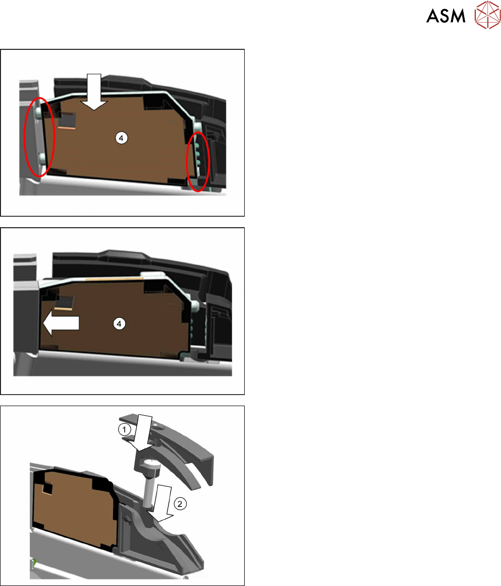
► Insert the splice sensor(4) in place of the
dummy, as shown.
Make sure that the 2 fixture pins point forwards
and the 3 contact pins point backwards.
► Push the splice sensor(4) forwards, in the direc-
tion of the arrow, as far as the stop.
► From above, insert the screw supplied "RF-
SN65-2.5 x 12-9.8" through the hole in the holder
on the insertion tunnel.(1)
► Fit the insertion tunnel onto the filler piece.(2)