Service Manual SIPLACE SmartFeeder.pdf - 第119页
7 Repairs to SmartFeeder 8 mm X / Xi 7.6 Splice sensor Service Manual SIPLACE SmartFeeder 4 - 8 mm X / Xi SIPLACE SmartFeeder 2 x 8 mm X / Xi 11/2020 119 ► Push the filling piece (1) to the side. ► Remove the splice sen…
7 Repairs to SmartFeeder 8 mm X / Xi
7.6 Splice sensor
118 Service Manual SIPLACE SmartFeeder 4 - 8 mm X / Xi SIPLACE SmartFeeder 2 x 8 mm X / Xi 11/2020
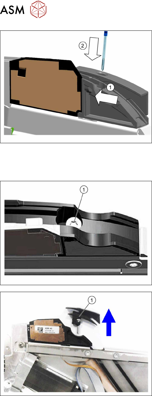
► Push the filler pieceand the insertion tunnel in
the direction of the arrow, towards the splice
sensor, as far as the stop.(1)
The splice sensor is automatically contacted by the
board on the filling piece and is then recognized by the
software.
► Fix the filler piece into place with the screw inser-
ted
and 0.6Nm.(2)
7.6.2 Replacing the splice sensor filling piece
7.6.2.1 Removing the splice sensor filling piece
► Remove the left side cover (see 7.3.1 "Removing
the Left Side Cover" [}102]).
► Place the feeder module in a stable, upright posi-
tion.
For feeder module without sensor insertion tunnel:
► Loosen and remove the TORX screw marked in
the diagram(1)
.
For feeder module with sensor insertion tunnel:
► Loosen the TORX screw.
► Lift the TORX screw and the sensor insertion tun-
nel(1)
up and out.
7 Repairs to SmartFeeder 8 mm X / Xi
7.6 Splice sensor
Service Manual SIPLACE SmartFeeder 4 - 8 mm X / Xi SIPLACE SmartFeeder 2 x 8 mm X / Xi 11/2020 119
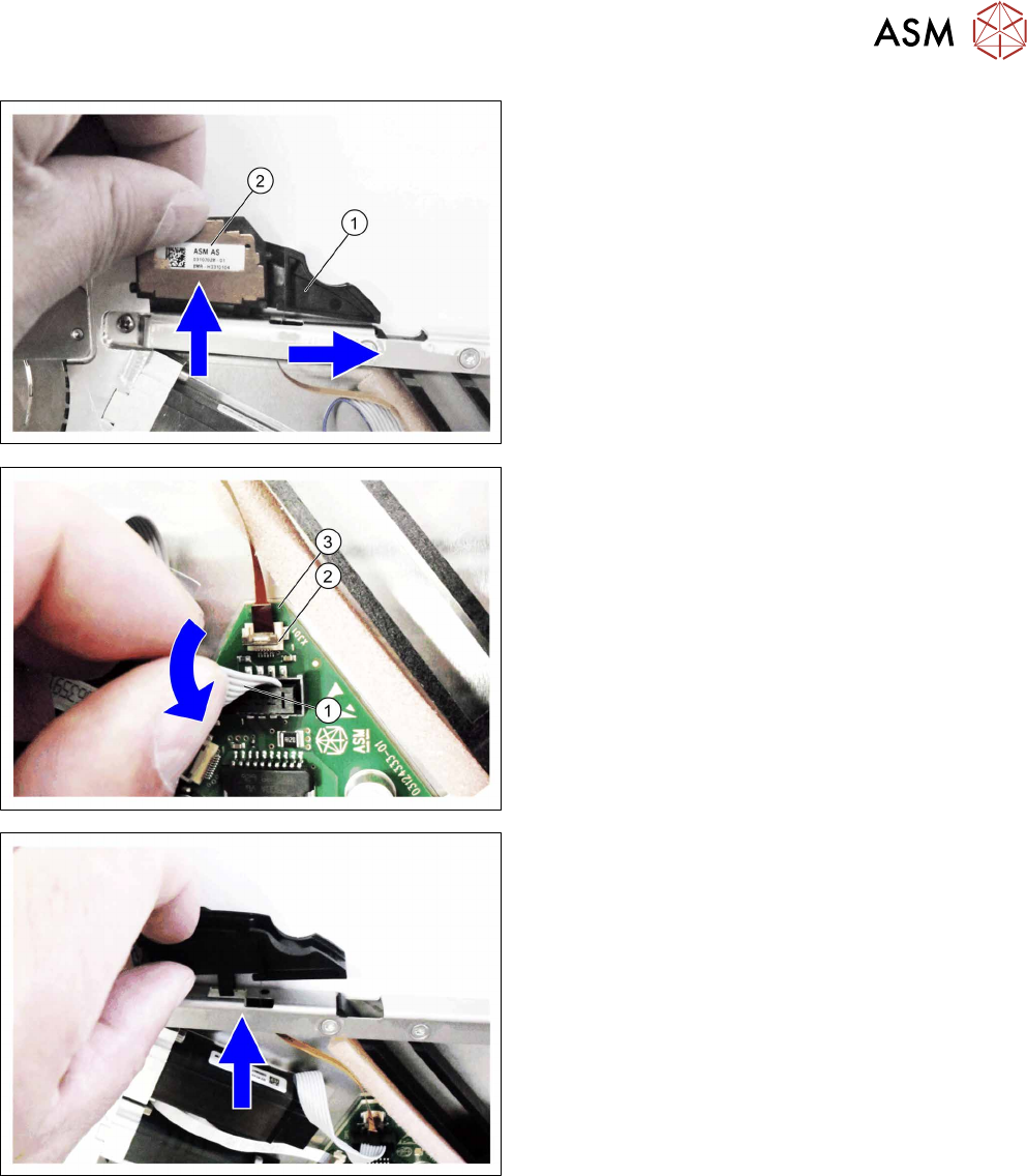
► Push the filling piece(1) to the side.
► Remove the splice sensor(2).
► Swing the motor cable(1) down so that you can
see the connection for the sensor cable(2)
.
► Open the connection on the sensor cable(2).
► Pull the sensor cable(3) out of the connection.
► Pull the filler piece and sensor able up and out of
the "top stiffener".
Make sure that the sensor cable remains undam-
aged during this.
7 Repairs to SmartFeeder 8 mm X / Xi
7.6 Splice sensor
120 Service Manual SIPLACE SmartFeeder 4 - 8 mm X / Xi SIPLACE SmartFeeder 2 x 8 mm X / Xi 11/2020
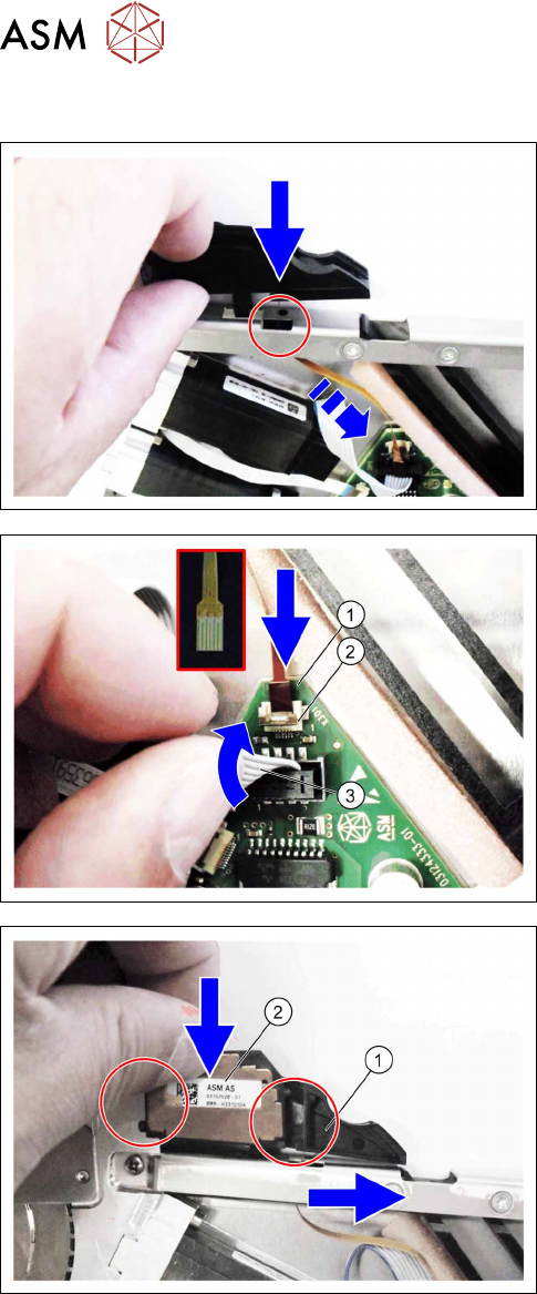
7.6.2.2 Fitting the splice sensor filling piece
► Push the sensor cable through the recess in the
"top stiffener".
► Fit the filler piece into the recess in the "top
stiffener", as shown.
► Push the sensor cable(1) as far as the stop into
the connection shown in the diagram X301(2)
.
Make sure that the contacts are on the underside
of the cable and that the brown side of the cable
can be seen on the top.
► Lock the connection.
► Press the motor cable(3) carefully up again and
over the connection X301.
► Push the filling piece(1) to the right.
► Insert the splice sensor(2).
Make sure that the 2 fixing pins are pointing to
the left and the 3 contact pins are pointing to the
right, towards the filler piece, during the insertion.