Service Manual SIPLACE SmartFeeder.pdf - 第12页
1 Introduction 1.7 Staff qualifications and training 12 Service Manual SIPLACE SmartFeeder 4 - 8 mm X / Xi SIPLACE SmartFeeder 2 x 8 mm X / Xi 11/2020

1 Introduction
1.7 Staff qualifications and training
Service Manual SIPLACE SmartFeeder 4 - 8 mm X / Xi SIPLACE SmartFeeder 2 x 8 mm X / Xi 11/2020 11
1.7 Staff qualifications and training
Qualified or adequately trained personnel means that these people are familiar with the setting up,
operation and maintenance of the machine and the add-on devices and are suitably qualified, e.g.:
●
Have been trained, instructed or authorized to switch on and off, isolate, earth and identify
electrical circuits and system components in accordance with normal safety standards.
●
Have been trained or instructed in the upkeep and use of appropriate safety equipment in
accordance with normal safety standards.

1 Introduction
1.7 Staff qualifications and training
12 Service Manual SIPLACE SmartFeeder 4 - 8 mm X / Xi SIPLACE SmartFeeder 2 x 8 mm X / Xi 11/2020
2 General
2.1 Requirements
Service Manual SIPLACE SmartFeeder 4 - 8 mm X / Xi SIPLACE SmartFeeder 2 x 8 mm X / Xi 11/2020 13
2 General
NOTICE
Area of application
The tasks described in this manual apply for the following areas:
- SIPLACE SmartFeeder 4mmX / Xi
- SIPLACE SmartFeeder 8mmX / Xi
- SIPLACE SmartFeeder 2x8mmX / Xi
The service work on the SIPLACE® feeder modules SmartFeeder 12–104mmX is de-
scribed in the service manual "SIPLACE SmartFeeder 12–104mm" (German [00198780-
xx], English [00198781-xx]).
2.1 Requirements
To correctly repair X feeder modules, you require an ESD-compatible workplace with a stable, level
and clean surface.
2.2 Warranty
CAUTION
Observe the clauses in the warranty agreements for your feeder.
On the bottom right side of the tape drive, you will find a warranty seal. If you still have a
valid warranty claim for the feeder module, this will be violated if you break the warranty
seal.
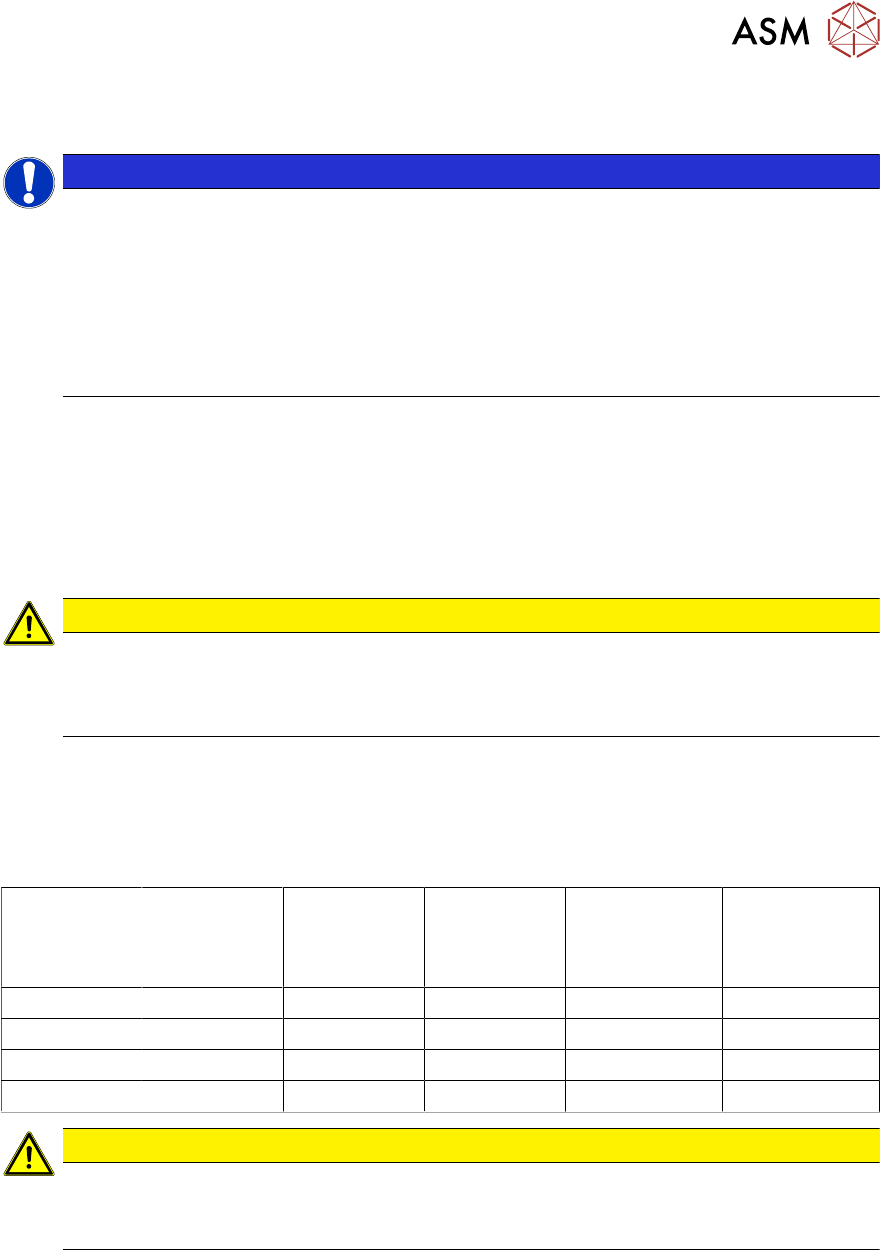
2.3 Equipment Required
Tools
You need the following tools to remove and fasten the spare parts described in this manual:
Torque screw
driver
Phillips
interchange-
able bit
Flat-bladed
interchange-
able bit
Allen key
interchange-
able bit
size 2
Allen key
interchangeable
bit
size 3
TORX
interchangeable
bit
size T8
0.2 Nm X
0.35 Nm X X
0.6 Nm X X X X
0.9 Nm X
CAUTION
Observe the torque
The torque screwdriver and interchangeable bits are delivered separately.
Make sure that the bits are assigned correctly during assembly work.
●
Flat-bladed screwdriver size 0
●
Flat-bladed screwdriver size 1
●
Phillips screwdriver
●
TORX screwdriver size T8
●
Allen key size 1.5
●
Angled Allen key, size 2
●
Allen key size 3
●
Allen key size 4