Service Manual SIPLACE SmartFeeder.pdf - 第158页
7 Repairs to SmartFeeder 8 mm X / Xi 7.16 Control board 158 Service Manual SIPLACE SmartFeeder 4 - 8 mm X / Xi SIPLACE SmartFeeder 2 x 8 mm X / Xi 11/2020 7.16.1 Removing the control board ► Carefully place the feeder mo…
7 Repairs to SmartFeeder 8 mm X / Xi
7.16 Control board
Service Manual SIPLACE SmartFeeder 4 - 8 mm X / Xi SIPLACE SmartFeeder 2 x 8 mm X / Xi 11/2020 157
7.16 Control board
CAUTION
Electrostatic charge
When removing and fitting the control board, observe the currently applicable ESD
guidelines.
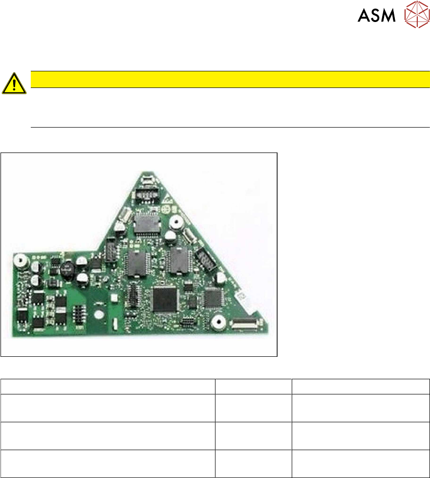
Required spare part
Fig.52: Example control board X8Smart V2
Feeder module Item no. Designation
SmartFeeder 8mmX (V1) 00141370-01
SmartFeeder 8mm X Splice (V1) 00141390-01
03101127-xx Control board X8Smart
SmartFeeder 8mmX (V2) 00141370-02
SmartFeeder 8mm X Splice (V2) 00141390-02
03124276-xx Control board X8Smart V2
SmartFeeder 8mm Xi [00141480-xx]
SmartFeeder 8mm Xi Splice [00141500-xx]
03160015-xx Control board X8Smart Xi
Tools required
●
Phillips screwdriver 0.9Nm
●
TORX screwdriver 0.6Nm and 0.2 Nm, size T8
7 Repairs to SmartFeeder 8 mm X / Xi
7.16 Control board
158 Service Manual SIPLACE SmartFeeder 4 - 8 mm X / Xi SIPLACE SmartFeeder 2 x 8 mm X / Xi 11/2020
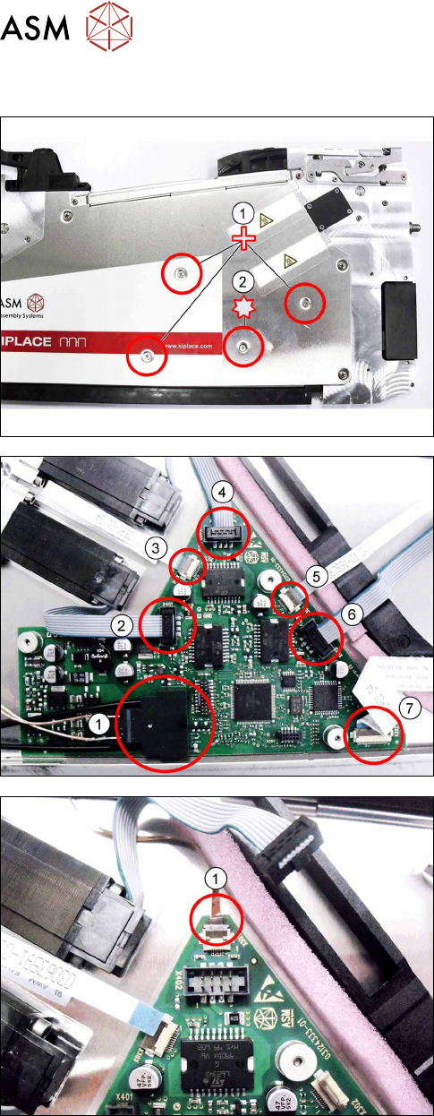
7.16.1 Removing the control board
► Carefully place the feeder module with the left
side down on a stable, level and clean surface.
► Remove the three Phillips screws marked in the
picture(1)
, which fasten the control board to the
right side cover.
► Carefully remove the TORX screw shown in the
diagram(2)
, which fastens the EDIF connector to
the control board.
Use a size 8 TORX screwdriver for this.
► Carefully place the feeder module with the right
side down on a stable, level and clean surface.
► Remove the left side cover (see section 7.3.1
"Removing the Left Side Cover" [}102]).
► Remove the EDIF connector(1).
► Loosen the 6 connections shown in the dia-
gram(2 – 7).
► If there is a splice sensor fitted in the feeder mod-
ule, open the connection to the splice sensor
cable.(1)
► Remove the control board.
7 Repairs to SmartFeeder 8 mm X / Xi
7.16 Control board
Service Manual SIPLACE SmartFeeder 4 - 8 mm X / Xi SIPLACE SmartFeeder 2 x 8 mm X / Xi 11/2020 159
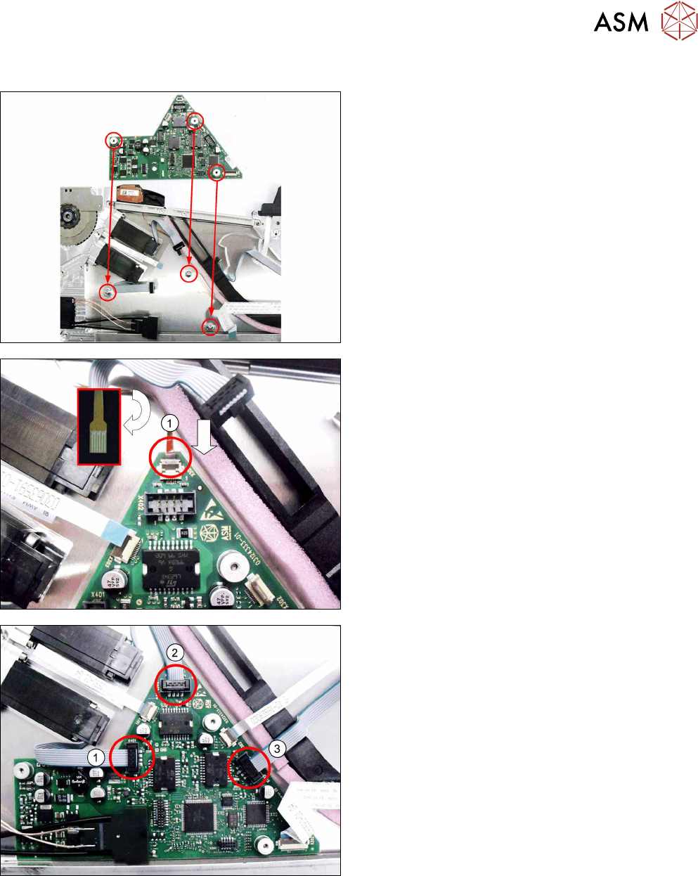
7.16.2 Fitting the control board
► Carefully place the feeder module with the right
side down on a stable, level and clean surface.
► Insert the control board into the feeder module as
shown in the diagram.
Align the position of the control board using the 3
holes in the control board and the 3 holes in the
side cover.
► Push the flat ribbon cable for the splice sensor as
far as the stop into the connection shown in the
diagram(1)
.
Make sure that the contacts are on the underside
of the cable and that the brown side of the cable
can be seen on the top.
► Lock the connection.
► Insert the connectors shown in the diagram(1-3)
into the relevant connections on the control
board.