Service Manual SIPLACE SmartFeeder.pdf - 第242页
8 Repairs to SmartFeeder 2x8 mm X / Xi 8.16 Handle with control panel 242 Service Manual SIPLACE SmartFeeder 4 - 8 mm X / Xi SIPLACE SmartFeeder 2 x 8 mm X / Xi 11/2020 ► Insert the control panel and board vertically int…
8 Repairs to SmartFeeder 2x8 mm X / Xi
8.16 Handle with control panel
Service Manual SIPLACE SmartFeeder 4 - 8 mm X / Xi SIPLACE SmartFeeder 2 x 8 mm X / Xi 11/2020 241
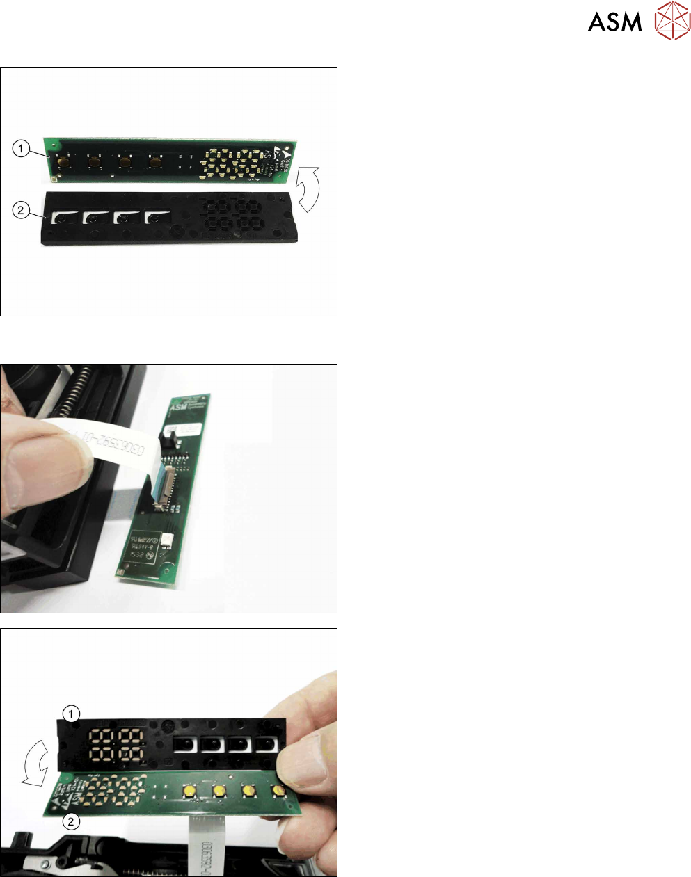
► Lift the printed circuit board off the control panel.
8.16.3.4 Fitting the control panel, board and control panel window
► Insert the end of the flat ribbon cable (with the
blue side pointing upwards as shown) straight
into the flat ribbon connection shown on the
board, as far as the stopper.
► Close the connection and make sure that the
cable it firmly fitted.
► Place the control panel(1) as shown in the dia-
gram onto the board(2)
8 Repairs to SmartFeeder 2x8 mm X / Xi
8.16 Handle with control panel
242 Service Manual SIPLACE SmartFeeder 4 - 8 mm X / Xi SIPLACE SmartFeeder 2 x 8 mm X / Xi 11/2020
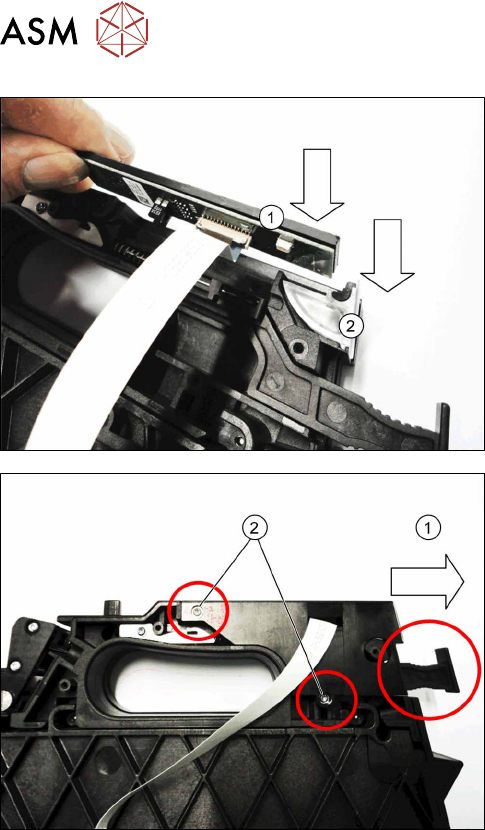
► Insert the control panel and board vertically into
the handle. (1)
► Insert the (new) control panel window from above
into the handle.(2)
► Push the cover plate on the flat ribbon cable
along the handle, until you can see the holes for
the screws through the cover plate.
► Release the removal handle lock, if neces-
sary.(1)
► Fasten the cover plate with the two screws
marked in the diagram.
Use a size T8 TORX screwdriver with 0.6 Nm for
this.

8 Repairs to SmartFeeder 2x8 mm X / Xi
8.17 Control board
Service Manual SIPLACE SmartFeeder 4 - 8 mm X / Xi SIPLACE SmartFeeder 2 x 8 mm X / Xi 11/2020 243
8.17 Control board
The control board for the SmartFeeder 2x8mmX is not available as a spare part, because the cali-
bration data for the pickup position are saved in the EEPROM of this board.
A new calibration of the pickup position is therefore only possible at the final inspection point of the
feeder module production at ASM.