Service Manual SIPLACE SmartFeeder.pdf - 第31页
6 Repairs to SmartFeeder 4 mm X / Xi 6.3 Side Covers Service Manual SIPLACE SmartFeeder 4 - 8 mm X / Xi SIPLACE SmartFeeder 2 x 8 mm X / Xi 11/2020 31 6.3.3 Removing the Right Side Cover NOTICE Avoiding damaging the boar…
6 Repairs to SmartFeeder 4 mm X / Xi
6.3 Side Covers
30 Service Manual SIPLACE SmartFeeder 4 - 8 mm X / Xi SIPLACE SmartFeeder 2 x 8 mm X / Xi 11/2020
6.3.1 Removing the Left Side Cover
NOTICE
Avoiding damaging the board
Before you remove the left side cover, make sure that the right side cover has been com-
pletely fixed in place with all screws. If not, the threaded bolts could be damaged on the
board.
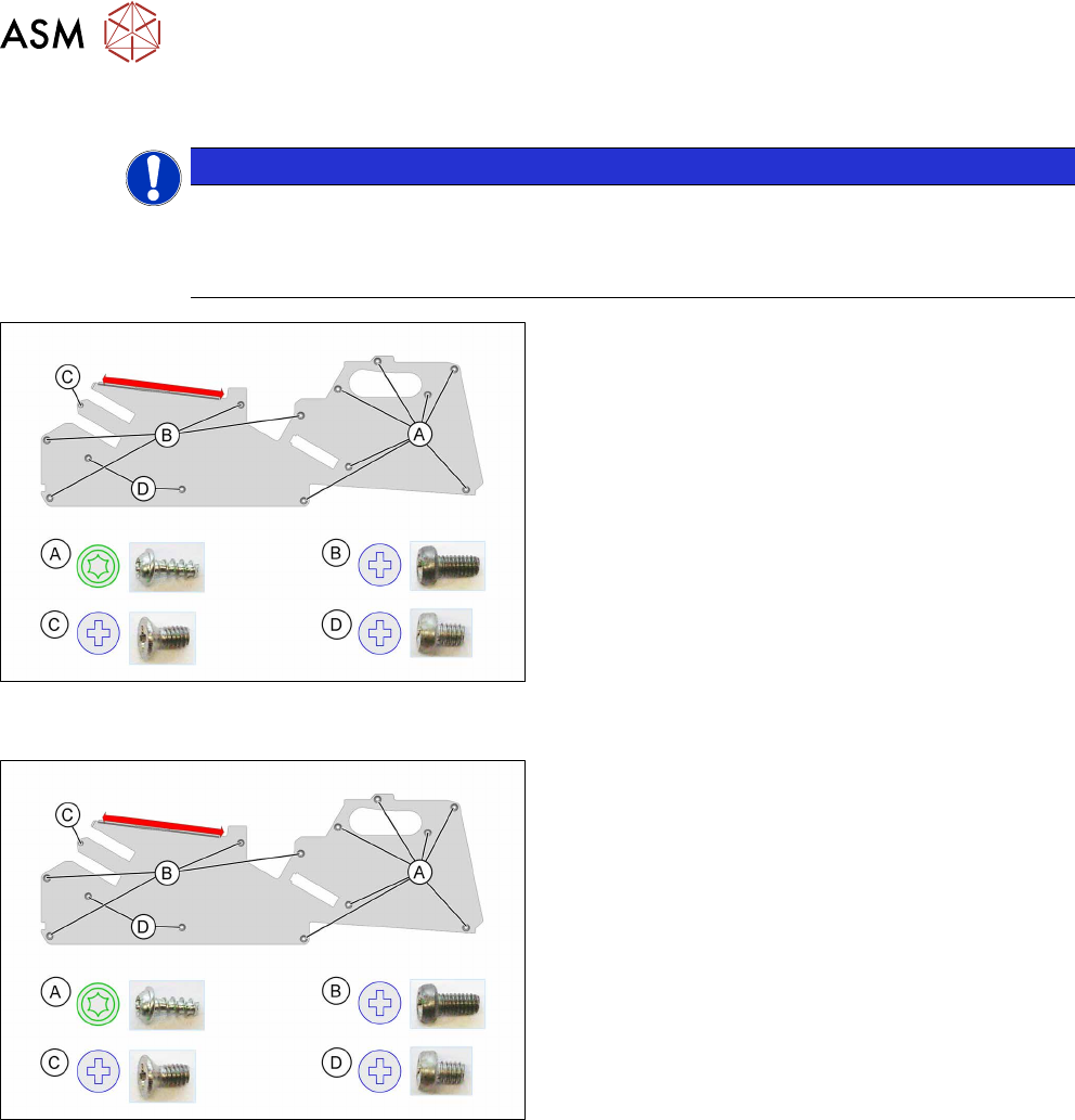
► Carefully place the feeder module with the right
side down on a stable, level and clean surface.
► Loosen the screws as shown in the diagram.
You need a TORX screwdriver for the screws marked
A
.
You need a Phillips screwdriver for the screws marked
B
, Cand D.
The side cover is only inserted in the upper part of the
frame in the area marked red.
► Pull the side cover down and out.
6.3.2 Fitting the Left Side Cover
► Carefully place the feeder module with the right
side down on a stable, level and clean surface.
► Push the side cover (area marked in red) under
the rail as shown, as far as the stop.
► Fix the screws as shown in the diagram. Begin
with the inner screws and work towards the out-
side.
You need a Phillips screwdriver with 0.9 Nm for the
screws marked B
, Cand D.
You need a TORX screwdriver with 0.6 Nm for the
screws marked A
.
6 Repairs to SmartFeeder 4 mm X / Xi
6.3 Side Covers
Service Manual SIPLACE SmartFeeder 4 - 8 mm X / Xi SIPLACE SmartFeeder 2 x 8 mm X / Xi 11/2020 31
6.3.3 Removing the Right Side Cover
NOTICE
Avoiding damaging the board
Before you remove the right side cover, make sure that the left side cover has been com-
pletely fixed in place with all screws. If not, the threaded bolts could be damaged on the
board.
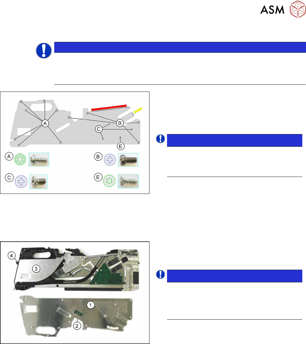
► Carefully place the feeder module with the left
side down on a stable, level and clean surface.
► First loosen screw E with a TORX screwdriver.
This screw fixes the EDIF connector on the main
board.
NOTICE!
To avoid damaging the connector, observe
the installation guide after this description
for the right side cover with the relevant
torques!
.
► Loosen the screws marked A with a TORX
screwdriver.
► Loosen the screws marked B and C with a
Philips screwdriver.
The side cover is only inserted in the upper part of the
frame in the area marked red.
► Pull the side cover down and out.
► Carefully lift the side cover (1).
► Place the side cover (1) with the board (2) facing
upwards on a clean and even surface.
NOTICE!
Please note that the foil container cover (3)
and the foil container flap (4) are only clipped
or placed on! Remove these two parts before
you change the position of the feeder mod-
ule.
.
A description of how to remove the cover and the foil
container flap can be found at 6.12.1
"Replacing the
flap on the drip tray and shaft" [}72].
6 Repairs to SmartFeeder 4 mm X / Xi
6.3 Side Covers
32 Service Manual SIPLACE SmartFeeder 4 - 8 mm X / Xi SIPLACE SmartFeeder 2 x 8 mm X / Xi 11/2020
6.3.4 Fitting the Right Side Cover
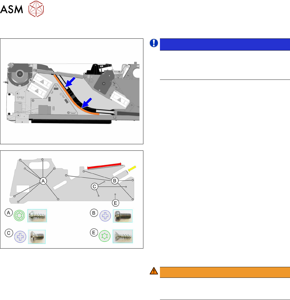
NOTICE!
Observe the correct position of the foam
seal. Make sure that the foam seal does not
get trapped in the empty tape duct or pro-
trude into it!
.
To check the correct position of the foam seal, remove
the left side cover, as shown (after fitting the right side
cover), and correct the position of the foam rubber if
necessary.
► Carefully place the feeder module with the left
side down on a stable, level and clean surface.
► Insert the side cover (in the area marked red), as
shown, under the rail, as far as the stop.
► Insert the side cover on the right side, in the area
marked yellow under the encoder.
► Fasten the screws as shown in the diagram. Be-
gin with the inner screws (C
) and work outwards
(B
+ A).
Fasten screw E
last.
You need a Phillips screwdriver with 0.6 Nm for the
screws marked B
and C.
You need a TORX screwdriver with 0.6 Nm for the
screws marked A
.
Also use a TORX screwdriver for the screw marked E.
WARNING!
Tighten screw E no more than hand-tight,
otherwise the screw fixtures inside the feeder
module could be damaged or broken.
.