Service Manual SIPLACE SmartFeeder.pdf - 第38页
6 Repairs to SmartFeeder 4 mm X / Xi 6.5 Pickup window 38 Service Manual SIPLACE SmartFeeder 4 - 8 mm X / Xi SIPLACE SmartFeeder 2 x 8 mm X / Xi 11/2020 ► Move the feeder module to a position where it is upright and stab…
6 Repairs to SmartFeeder 4 mm X / Xi
6.5 Pickup window
Service Manual SIPLACE SmartFeeder 4 - 8 mm X / Xi SIPLACE SmartFeeder 2 x 8 mm X / Xi 11/2020 37
6.5.1 Removing the Pickup Window
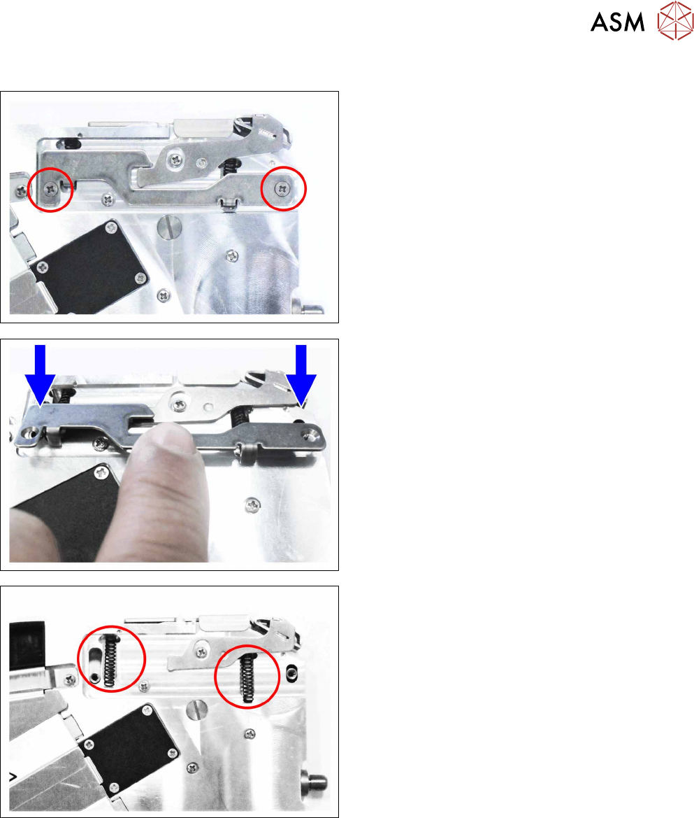
► Carefully place the feeder module with the left
side down on a stable, level and clean surface.
► Remove the two Phillips screws.
► Remove the counterplate.
► Remove the two pressure springs.
6 Repairs to SmartFeeder 4 mm X / Xi
6.5 Pickup window
38 Service Manual SIPLACE SmartFeeder 4 - 8 mm X / Xi SIPLACE SmartFeeder 2 x 8 mm X / Xi 11/2020
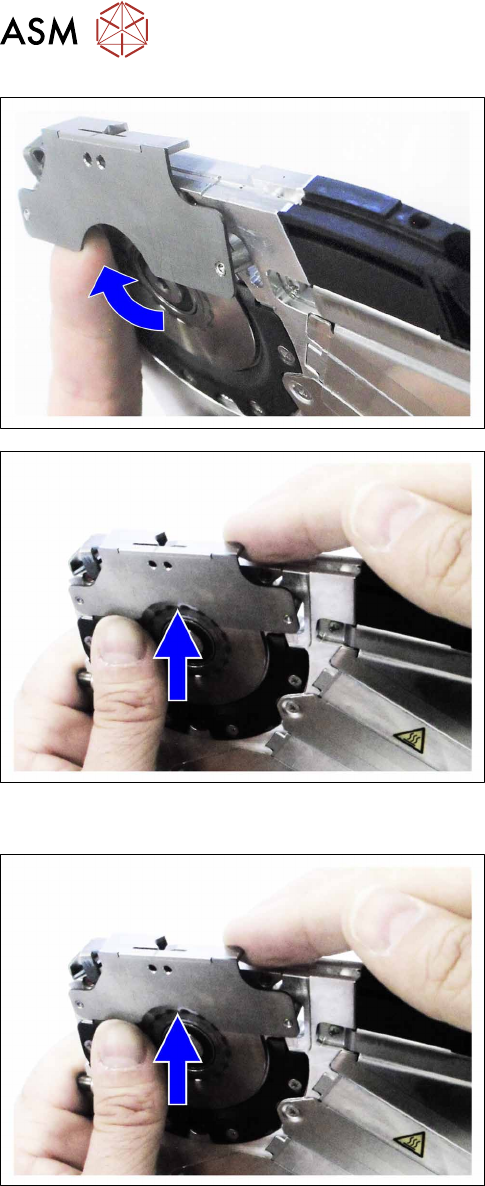
► Move the feeder module to a position where it is
upright and stable.
► Press the pickup window slightly upwards.
► Carefully lift the pickup window over the pin
wheel.
► Remove the pickup window from the left side.
6.5.2 Fitting the pickup window
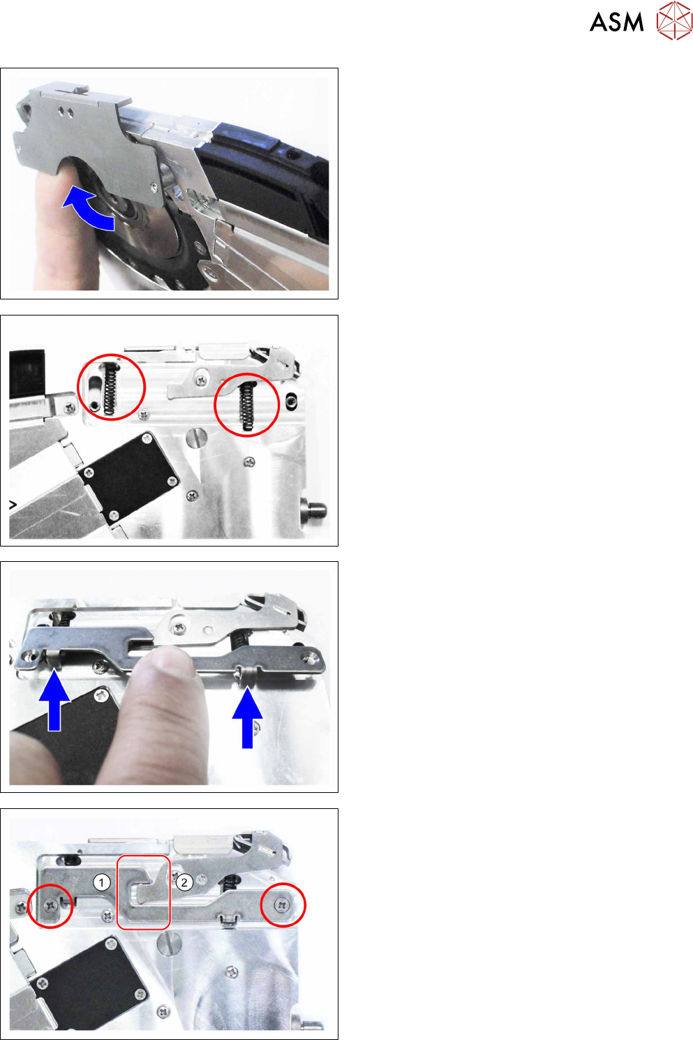
► Move the feeder module to a position where it is
upright and stable.
► Carefully lift the pickup window from the lefthand
side over the pin wheel.
6 Repairs to SmartFeeder 4 mm X / Xi
6.5 Pickup window
Service Manual SIPLACE SmartFeeder 4 - 8 mm X / Xi SIPLACE SmartFeeder 2 x 8 mm X / Xi 11/2020 39
► Press the pickup window slightly upwards and
push it into the prescribed position.
► Carefully place the feeder module with the left
side down on a stable, level and clean surface.
► Insert both pressure springs.
Make sure that the bottom ends of the pressure
springs are not inserted into the groove.
► Insert the nibs of the counterplate into the bottom
ends of the pressure springs.
► Carefully push the counterplate upwards, until
both of the counterplate nibs engage with the
pressure springs in the pickup window.
► Push the counterplate upwards even more, until
the threaded holes of the pickup window are
completely visible in the holes of the counter-
plate.
Make sure that you do not get the counter-
plate(1)
and the actuator(2) jammed against one
another in the marked area.
► Fix the counterplate into place with the two Phil-
lips screws marked.